Handleiding
Je bekijkt pagina 53 van 60
53
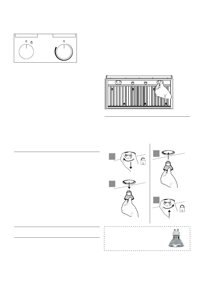
Panel de control de la campana extractora.
El panel de control está en el centro de la parte
inferior del extractor.
Botónparaencender/apagarlaluz(A)
Interruptor de encendido/apagado de las luces. La
posición «0» apaga las luces, girar el interruptor
hacia la derecha las enciende.
Botónparaencender/apagarelventilador(B)
Interruptor de encendido/apagado del ventilador.
Mueva el control hacia la derecha para encender
el ventilador y variar la velocidad del ventilador.
Gire a la izquierda a «0» para apagarlo.
Para un mejor resultado
Encienda la campana extractora durante algunos
minutos antes de cocinar para crear un ujo de
aire adecuado. Deje que la unidad funcione unos
minutos después de terminar de cocinar para
eliminar todo el humo y los olores de la cocina.
Limpieza
Los ltros de grasa y los raíles para grasa de
acero inoxidable se deben limpiar frecuentemente
en una solución de detergente caliente o lavar en
el lavavajillas. Limpie las supercies exteriores
con un limpiador de acero inoxidable disponible
comercialmente. Los agentes abrasivos y
desengrasantes pueden rayar los acabados en
acero inoxidable, por lo que no se deben utilizar
para limpiar las supercies acabadas.
Asegúrese de que los ltros de grasa estén
completamente secos, si nada de agua, antes de
volver a colocarlos en el extractor.
Instalación/Desmontaje del raíl para grasa y
losltrosdegrasa
Version 07/11 - Page 11
Light On/Off Button (A)
On/Off switch for the halogen lights. Position "0" turns the lights off,
turning the switch to the right one click is the dimmer position, and
the next click to the right is full power
Blower On/Off Button (B)
On/Off switch for the blower. Move the dial to the right to turn the
blower ON and vary the speed of the blower. Turn to the left at "0"
to turn it OFF.
For Best Result
Start the rangehood several minutes before cooking to develop proper
airflow. Allow the unit to operate for several minutes after cooking is
complete to clear all smoke and odors from the kitchen.
Cleaning
The stainless steel grease filters and grease rail should be cleaned
frequently in hot detergent solution or washed in the dishwasher.
Clean exterior surfaces with a commercially available stainless steel
cleaner. Abrasives and scouring agents can scratch stainless steel
finishes and should not be used to clean finished surfaces.
Grease rail and Grease Filter Installation / Removal
Remove the plastic from the filter, the knobs need to be installed
onto the filter with 2 screws to each filter
Install the grease rail into the back of the hood, into the slots on the
inside floor of the rear of the hood. The Grease filters should be
installed before operating the rangehood. To install the filters, use the
two knobs (in FIGURE 28) to hold the filter and insert the filter into
the front edge of the hood with the knobs facing out into the spring
loaded slot. Install the other end of the filter above the grease rail in
the back of the hood.
USE AND CARE INFORMATION
This rangehood system is designed to remove smoke, cooking vapors
and odors from the cooktop area.
Rangehood Control Panel
The control panel is located in the center of the hood bottom. The
position and function of each control button are indicated in FIGURE
27
FIGURE 28
Replacing the Halogen Lamp
Before you begin, make sure that the rangehood is turned off and
that the other lamps have had sufficient time to cool. Halogen lamps
burn extremely hot and serious injury could result from touching a hot
lamp. Press and twist the lamp to remove. Then remove the lamp
and replace with a new lamp.
WIRING DIAGRAM
This rangehood uses 45 watt PAR16
Halogen Lamps.
FIGURE 27
FIGURE 26
ALL INSTALLATIONS
1. Use a drill to install side rails on the inside rangehood walls to
line the inside hood wall with stainless, 2 and 3 in FIGURE 26 with
9a. screws, 4 screws total.
BLK
WHT
R11B41
LIGHT CONTROL
OFF / HALF LIGHT / ON
1
Y-G
A
RED
WIRING BOX
WHT
BLK
BLK
23
B
ORG
WHT
4
VLT
N
L
Y-G
LINE IN
120Vac
60Hz ~
Y-G
BLU
123
654
789
123
654
987
RED
M8 4V
120V ~
WHT
BRW
BLU
BLK
ORG
BLU
BLK
Y-G
Y-G
ON/OFF MOTOR
SPEED CONTROL
BLKBLK
BLU
123
654
789
123
654
987
RED
M8 4V
120V ~
BLU
Y-G
WHT
BRW
BLKBLK
BLU
123
654
123
654
BLK
ORG
Y-G
BLU
WHT
BLK
Y-G
WIRING BOX FOR
REMOTE BLOWER
WHT
REMOTE
BLOWER
123
654
WHT
Y-G
BLKBLK
Y-G
9a
9a
2
3
9a
9a
Unidad de iluminación
• Sustituya la luz por una nueva del mismo tipo,
asegurándose de que coloca dos pasadores
de manera adecuada en los alojamientos del
soporte de la luz.
Retireelplásticodelltro,hayqueinstalarlos
pomosenelltrocon2tornillosencadaltro.
Instale el raíl para grasa en la parte trasera del
extractor, en las ranuras en el suelo exterior de
la parte trasera del extractor. Los ltros de grasa
de deben instalar antes de utilizar la campana
extractora. Para instalar los ltros, utilice los
dos pomos para sujetar el ltro e insertarlo en el
extremo delantero del extractor, con los pomos
mirando hacia fuera de la ranura accionada por
muelle. Instale el otro extremo del ltro debajo del
raíl para grasa, en la parte trasera del extractor.
A B
Lámparas led autobalastradas
Gu10 - listadas de acuerdo con
ul 1993/nmx-j-578/1-ance/csa
c22.2 No. 1993
a
b
a
b
Bekijk gratis de handleiding van Faber INPL3019SSNB-B, stel vragen en lees de antwoorden op veelvoorkomende problemen, of gebruik onze assistent om sneller informatie in de handleiding te vinden of uitleg te krijgen over specifieke functies.
Productinformatie
| Merk | Faber |
| Model | INPL3019SSNB-B |
| Categorie | Afzuigkap |
| Taal | Nederlands |
| Grootte | 8456 MB |


