Handleiding
Je bekijkt pagina 48 van 60
48
5
5
4
4
9c
INSTALACIÓNCONELVENTILADORREMOTO(RB900/RB1200)OVENTILADOREN
LÍNEA(INLBKIT)
NOTA: SIGA LAS INSTRUCCIONES QUE SE INCLUYEN CON EL VENTILADOR
REMOTO PARA INSTALAR EL VENTILADOR EN LA PARTE EXTERIOR DE SU CASA.
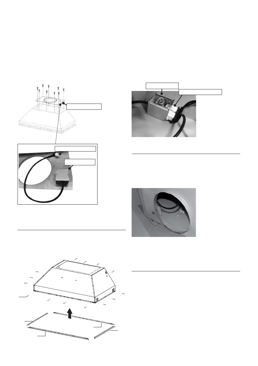
1. Instale la Placa B con la segunda caja de cables
(Figura 13) que viene con el kit de ventilador remoto,
en la parte superior de la campana extractora.
Utilice 9 tornillos que se proporcionan con el kit del
ventilador. Quite el oricio de montaje troquelado
eléctrico de la parte superior de la placa.
2. Retire la cubierta de plástico blanca e instale las
4 piezas laterales de la moldura (4-5)
en la parte
exterior del extractor utilizando (14) los tornillos
parte 9c, consulte la instalación del raíl lateral en
(Figura 14).
FIGURE 14
3. Conecte el cable que proviene de la segunda caja
de cables al extremo de 6 oricios de la primera caja
de cables.
Conecte el cable que proviene de la caja negra del
tablero electrónico al extremo de 9 oricios de la
primera caja de cables (Figura 15).
4.
Pase el cable del ventilador remoto a través del
oricio de montaje
troquelado
en el paso 1
(Figura
13, 16). Conecte este cable del ventilador remoto a
la segunda caja de cables ubicada en la supercie
inferior de la placa B.
5. Siga el paso 4 en la página 14 para conectar
los conductos y los cables y probar la conexión
eléctrica. Utilice la caja de cables conectada en
la pared interior del extractor que se conecta a
la fuente de alimentación de la casa a través del
troquel en el lateral del extractor.
Version 07/11 - Page 10
INSTALLATION WITH REMOTE BLOWER (RB900 / RB1200)
OR IN-LINE BLOWER (INLBKIT)
NOTE: FOLLOW THE INSTRUCTIONS INCLUDED WITH THE
REMOTE BLOWER TO INSTALL THE BLOWER ON THE
OUTSIDE OF YOUR HOME
.
1. Install the Plate B (FIGURE 21) which came with the remote
blower kit, on top of the rangehood. Use 9 screws supplied with
the blower kit. Remove the electrical knockout hole on top of the
plate.
2. Remove the white plastic covering and Install the 4 side trim
pieces to the outside of the hood using (16) part 9b screws, see
the side rail installation in (FIGURE 22).
FIGURE 23
FIGURE 24
4. Feed the remote blower cable thru the knockout hole in step 1
(FIGURE 24). Connect the power supply cable from the remote
blower to the wiring box on the top ducting plate of the hood. Use
step 6 on page 8 and the diagram on page 8 (FIGURE 13)
5. Attach the hood to the cabinet using (12) 9c. screws to the
cabinet. FIGURE 25
6. Follow steps 6 - 9 on page 8 to connect ducting, wiring, and
test the electrical connection. Use the wiring box connected to
the inside wall of the hood which connects to the home power
supply thru the knockout on the side of the hood.
FIGURE 21
FIGURE 22
3. Connect the wire coming out of the wiring box on the top duct
plate to the light panel 6 hole slot connector on the front inside
of the hood (FIGURE 23)
FIGURE 25
B
FIGURE 16
Version 07/11 - Page 10
INSTALLATION WITH REMOTE BLOWER (RB900 / RB1200)
OR IN-LINE BLOWER (INLBKIT)
NOTE: FOLLOW THE INSTRUCTIONS INCLUDED WITH THE
REMOTE BLOWER TO INSTALL THE BLOWER ON THE
OUTSIDE OF YOUR HOME
.
1. Install the Plate B (FIGURE 21) which came with the remote
blower kit, on top of the rangehood. Use 9 screws supplied with
the blower kit. Remove the electrical knockout hole on top of the
plate.
2. Remove the white plastic covering and Install the 4 side trim
pieces to the outside of the hood using (16) part 9b screws, see
the side rail installation in (FIGURE 22).
FIGURE 23
FIGURE 24
4. Feed the remote blower cable thru the knockout hole in step 1
(FIGURE 24). Connect the power supply cable from the remote
blower to the wiring box on the top ducting plate of the hood. Use
step 6 on page 8 and the diagram on page 8 (FIGURE 13)
5. Attach the hood to the cabinet using (12) 9c. screws to the
cabinet. FIGURE 25
6. Follow steps 6 - 9 on page 8 to connect ducting, wiring, and
test the electrical connection. Use the wiring box connected to
the inside wall of the hood which connects to the home power
supply thru the knockout on the side of the hood.
FIGURE 21
FIGURE 22
3. Connect the wire coming out of the wiring box on the top duct
plate to the light panel 6 hole slot connector on the front inside
of the hood (FIGURE 23)
FIGURE 25
B
FIGURE 13
2ª caja de cables
2ª caja de cables
Extremode6oricios
FIGURE 15
1ª caja de cables
Extremode6oricios
Bekijk gratis de handleiding van Faber INPL3019SSNB-B, stel vragen en lees de antwoorden op veelvoorkomende problemen, of gebruik onze assistent om sneller informatie in de handleiding te vinden of uitleg te krijgen over specifieke functies.
Productinformatie
| Merk | Faber |
| Model | INPL3019SSNB-B |
| Categorie | Afzuigkap |
| Taal | Nederlands |
| Grootte | 8456 MB |


