Extron HC 402 handleiding
Handleiding
Je bekijkt pagina 2 van 16
2
HC 402 • Setup Guide (Continued)
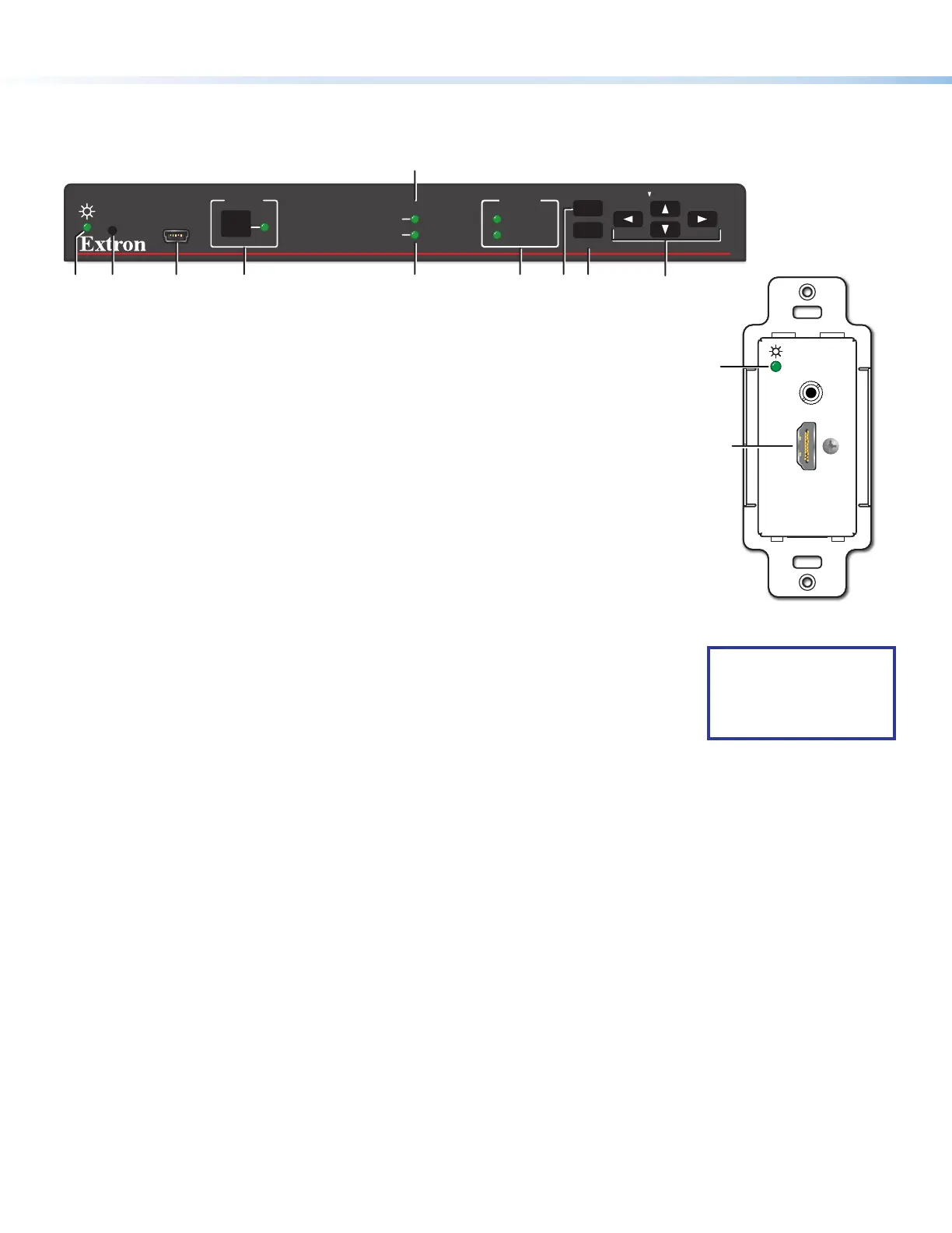
Panels and Features
Front Panel Features
CONFIG
HCR 102
1
INPUT
LPCM-2CH
MULTI-CH
HDCP
SIGNAL
R
MENU
ENTER
HOLD FOR 720p/1080p
1
AUDIO
HC
R 102
AI
J
B
C
D
HFGE
Figure 2. HCR102 Front Panel (Above),
HCT101D Front Panel Without Wallplate (Right)
A
Configuration (Config) connector (USB mini-B), page 11
B
Input selection button and LED, page 13
C
Input signal presence (Signal) LED, page 13
D
HDCP status LED, page 13
E
Audio input type LEDs (LPCM-2Ch and Multi-Ch, page 14)
F
Menu button,
G
Enter button, and
H
Navigation (right , left , up
, and down arrow) buttons (see
To configure the AV settings using the OSD and front panel buttons: on
page7)
I
Power LED (HCT101D), power and reset indicator LED (HCR102) —
This green LED indicates either the power status of the HCT101D transmitter or
the HCR102 receiver, or the reset mode of the receiver. For LED indications, see
the table below.
J
Reset button (HCR102) — Pressing this recessed button causes various product
settings to be reset to the factory defaults (see Reset Modes: a Brief Summary on
page15).
Reset and power LED (
I
) indications are as follows:
NOTE: For other
connectors on the
HCT101D, see Rear
and Side Panel
Features on page3.
HCT 101 D Transmitter HCR 102 Receiver
• Off — The unit is not powered on.
• On, lit amber — The unit is powered on
but there is no active signal at that input.
• On, lit green — The unit is powered on
and there is an active signal at that input.
• Off — The unit is not powered on.
• On, lit steadily — The unit is powered on.
• Blinking — The unit is powering up or the HCR102 is performing a reset.
The blink pattern depends on the selected reset mode.
For full descriptions of reset modes, how to use the reset button to activate
them, and details of LED indications of each mode, see the HC400 Series
User Guide.
Rear and Side Panel Features
POWER
12V
2.0A MAX
INPUTS
OUTPUTS
1
TP
HDMI
LR
AUDIO
HDMI/CEC
SIG
LINK
IN
COMIR DIGITAL I/O
12SGTx Rx GG34G
HCR 102
LAN
MAC: 00-05-A6-XX-XX-XX
S/N: ####### E######
00-05-A6-XX-XX-XX
A F ND G H
K L M
HCR 102 Rear
O
Figure 3. HCR102 Rear Panel
A
Power input connectors, page 12
B
Audio input connector, page 9
D
HDMI input connectors, page 10
E
Transmitter output RJ-45
connector (twisted pair
interconnection),
page 10
F
Receiver input RJ-45 connector
(twisted pair interconnection),
page 10
G
HDMI/CEC output connector,
page 10
H
Analog audio output connector,
page 10
K
COM RS-232 control port,
page 11
L
IR output control port, page 11
M
Digital I/O (digital input/output)
control ports, page 11
N
LAN (Ethernet) connector and
LEDs, page 11
O
MAC address (on side of receiver),
page 11
NOTE: Features
C
,
I
, and
J
are
available on other HC400 Series
transmitter models.
HCT 101 D
POWER
12V
A MAX
0.7
OUT
e
HDMI IN
AUDIO IN
e
HDMI
IN
A
UDI
O
IN
B
D
HCT 101 D Front
HCT 101 D
Rear
HCT 101 D
Right Side
HCT 101 D Top
Wallplate
A
E
E
Figure 4. HCT101D Right Side Panel (Top Left), Rear Panel (Top Right),
Top Panel (Bottom Left), Front Panel (Bottom Right)
e
HDMI IN
AUDIO IN
HCT 101 D Front
(Without Wallplate)
I
Input
2
Bekijk gratis de handleiding van Extron HC 402, stel vragen en lees de antwoorden op veelvoorkomende problemen, of gebruik onze assistent om sneller informatie in de handleiding te vinden of uitleg te krijgen over specifieke functies.
Productinformatie
| Merk | Extron |
| Model | HC 402 |
| Categorie | Niet gecategoriseerd |
| Taal | Nederlands |
| Grootte | 3565 MB |


