Extron ECM S10 handleiding
Handleiding
Je bekijkt pagina 2 van 14
2
ECM S10 Partition Sensor • Setup Guide (Continued)
Front Panel
w
RESET
BUS ID
RX
1
M
S
B
L
S
B
EU /
MK
NORTH
AMERICA
e
w
RESET
BUS ID
TX
1
M
S
B
L
S
B
EU /
MK
NORTH
AMERICA
e
CC
B
B
A
A
D
D
1
12
23
3
w
RESET
BUS ID
RX
1
M
S
B
L
S
B
EU /
MK
NORTH
AMERICA
HH
GG
D L
MINMAX
EE
F
F
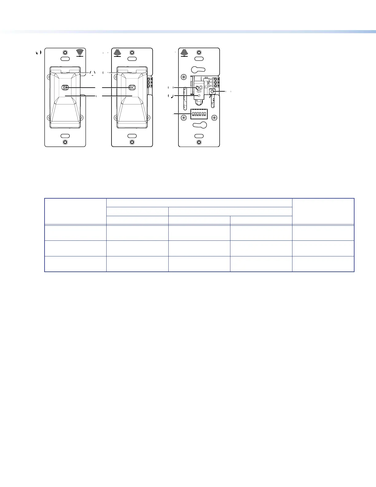
Figure 2. Front Panel Features of ECM S10
A
IR Signal Source — The transmitter emits an IR signal through this slot in the cover.
B
IR Signal Detector — The receiver detects the IR signal from the transmitter, when it passes through this slot in the cover.
C
Sensor Status LEDs — The transmitter has one red LED. The receiver has one amber and one green LED. These provide
feedback about the power and alignment status:
Sensor Set to Normally Open (D)
Digital OutputTransmitter LED Receiver LEDs
Red LED Amber LED Green LED
Sensors aligned and
partition open
ON OFF ON Open/Logic High
Partition closed
ON ON ON
Closed/Logic Low/
Ground
Sensors not aligned
and partition open
ON ON ON
Closed/Logic Low/
Ground
If the red transmitter LED is off, the transmitter is not receiving power.
If the green receiver sensor LED is off, the receiver is not receiving power.
D
Removable Sensor Cover — Both the transmitter and receiver have sensor covers. They are removed by gently pressing the
sides of the sensor cover to free the catches on both sides from the slots in the metal mounting plate. The cover can then be
pulled straight out.
Removing the cover from the receiver provides access to the BUS ID DIP switches, the sensitivity adjustment control, the
sensor setting control, and Reset button.
E
Sensitivity adjustment — By default, the sensitivity of the detector in the receiver is set to maximum. Extron recommends
that it remains at this setting.
F
Sensor Setting — By default, this is set to D (normally open). If required, use a small, at-bladed screwdriver to turn the
setting to L (normally closed).
G
BUS ID DIP Switches — Up to eight partition sensors congured for eBUS operation can be connected to one control
processor. Each eBUS device connected to the same control processor must have a unique BUS ID, which is set using the
DIP switches (see Step 3 — Setting the BUS ID Addresses on page 9).
H
Reset Button — If required, press this recessed button to reset the rmware to the factory installed version.
To reset the firmware
1. Disconnect the eBUS cable that is providing power.
2. Press and hold down the Reset button and, while holding down the Reset button, reconnect eBUS cable.
3. Release the Reset button 1 second after reconnecting power. When the eBUS Connection Status LED lights, the reset
process is complete.
If the reset is carried out while the ECM S10 is sending the partition status signal via I/O ports (no control signal via eBUS),
the rmware is reset to the factory default. However, if the reset is carried out while the partition status signal is sent via
eBUS, the rmware is initially reset to the factory default but the IPCP control processor may then push a more recent version
of the rmware to the ECM S10.
figure 2
1
Transmitter with sensor cover
2
Receiver with sensor cover
3
Receiver with cover removed.
Bekijk gratis de handleiding van Extron ECM S10, stel vragen en lees de antwoorden op veelvoorkomende problemen, of gebruik onze assistent om sneller informatie in de handleiding te vinden of uitleg te krijgen over specifieke functies.
Productinformatie
| Merk | Extron |
| Model | ECM S10 |
| Categorie | Niet gecategoriseerd |
| Taal | Nederlands |
| Grootte | 3220 MB |


