Extron ACP 106 EU handleiding
Handleiding
Je bekijkt pagina 3 van 8
3
6. To remove a button, press a button backward through its slot in the button plate until the
membrane containing the button is free.
7. To replace a button, align the two pegs in the button membrane with the holes located at
opposite corners of the empty slot on the back of the button faceplate and push the button
forward so it ts in the desired slot (see the gure to the right). Ensure the button text
orientation is correct.
8. Press the button into the button plate until the pegs on the membrane are seated in the
corresponding holes.
9. Repeat steps 6 through 8 for any other buttons being replaced.
10. Align the back of the button plate with the control plate and press it into place. The four
tabs released in steps 2 through 4 snap back into place.
11. Ensure the plastic faceplate and metal mounting plate are in the correct orientation. To reattach the plastic faceplate, press
the faceplate back into the metal mounting plate, using the two catches released in step 1.
Step 4: Set Bus ID Addresses
ACP
+S -S G+V
+V+S -S G
R
PWR LOAD
= 1.5W
STATUS
GREEN
AMBER
RED
LINK
COM ERROR
ID ERROR
+
V
+
S G
–
S
010010
ON
123456
000001
1
ON
123456
18Unit address
DIP switches
Binary address
ACP port on a
DMP Plus, or on
another ACP
endpoint
ACP Ports
• Connect up to eight (8) ACP endpoint devices per
DMP Plus.
• Wire the connectors the same at both ends.
• These ports are identical. You can connect devices
interchangeably to either port.
• Do not exceed a total of 1000 feet (305meters) of cable for
connections between the DMP Plus and all of the ACP
panels.
• Power is provided by the DMP Plus, a PS 1220EB power
inserter, or an Extron 12 VDC power supply.
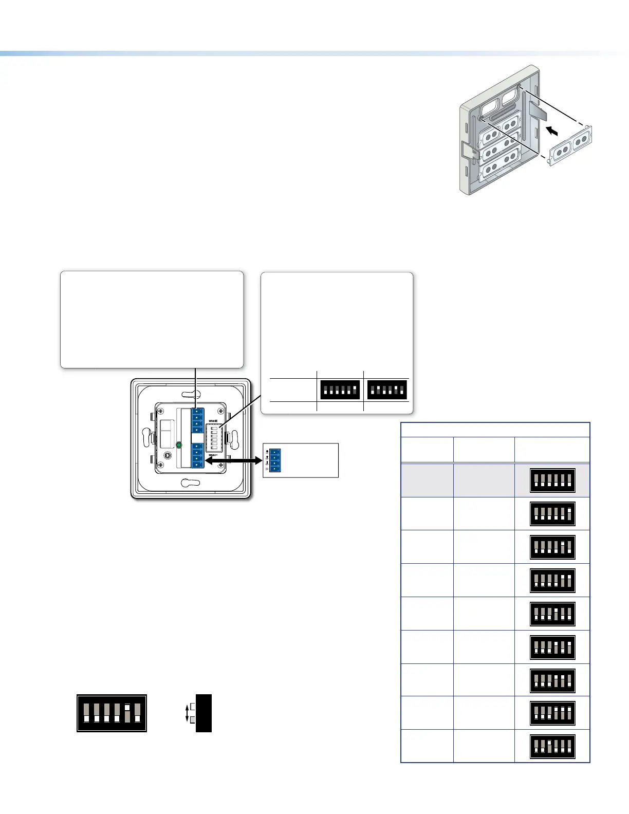
Bus ID Address DIP Switches
• Use these DIP switches to set the six-bit, binary
bus address for the ACP 106 EU/MK.
• Each ACP connected to the same DMP Plus
must have a unique address.
• Switch 1 (on the left) is the highest value (32, the
the most signicant bit [labeled “MSB”]).
• Switch 6 (on the right) is the lowest (1, the least
signicant bit [labeled “LSB”]).
• Up = on = 1, Down = off = 0
Examples:
Figure 3. ACP 106 EU/MK Rear Panel and Bus ID DIP Switch Assembly
Set the bus identication (bus ID) DIP switches for the ACP 106 EU/MK and
any other ACP panels being connected to the system. Each ACP device
must have a unique bus ID. If multiple panels have the same bus ID, address
conicts may cause one or more of the panels to not be recognized in DSP
Congurator or by the host device. Up to eight ACP devices can be connected
in the same system.
Each ACP device in a system must have a unique six-digit binary bus ID. ACP
bus IDs are set using the DIP switch assembly on the rear panel of the ACP
106 EU/MK (see gure 3).
Switch 1 on the left sets the most signicant bit (highest number, 32) while
switch 6 on the right sets the least signicant bit (the lowest number, 1). See
the example addresses to the right.
Slide
1 2
3
4
56
ON
M
S
B
L
S
B
BUS ID
Example Addresses
Bus ID
(Decimal)
Binary
Address
DIP Switch
Setting
0 000000*
1 2
3
4
56
ON
M
S
B
L
S
B
1 000001
1 2
3
4
56
ON
M
S
B
L
S
B
2 000010
1 2
3
4
56
ON
M
S
B
L
S
B
3 000011
1 2
3
4
56
ON
M
S
B
L
S
B
4 000100
1 2
3
4
56
ON
M
S
B
L
S
B
5 000101
1 2
3
4
56
ON
M
S
B
L
S
B
6 000110
1 2
3
4
56
ON
M
S
B
L
S
B
7 000111
1 2
3
4
56
ON
M
S
B
L
S
B
8 001000
1 2
3
4
56
ON
M
S
B
L
S
B
*Address 000000 is reserved for the control processor and cannot be used by any ACP devices.
Bekijk gratis de handleiding van Extron ACP 106 EU, stel vragen en lees de antwoorden op veelvoorkomende problemen, of gebruik onze assistent om sneller informatie in de handleiding te vinden of uitleg te krijgen over specifieke functies.
Productinformatie
| Merk | Extron |
| Model | ACP 106 EU |
| Categorie | Niet gecategoriseerd |
| Taal | Nederlands |
| Grootte | 1886 MB |
Caratteristiche Prodotto
| Kleur van het product | Black, White |
| Gewicht | 100 g |
| Breedte | 81 mm |
| Diepte | 10 mm |
| Hoogte | 81 mm |


