EPEVER Tracer 4210AN handleiding
Handleiding
Je bekijkt pagina 12 van 40
8
24V
1
1
-
-
-
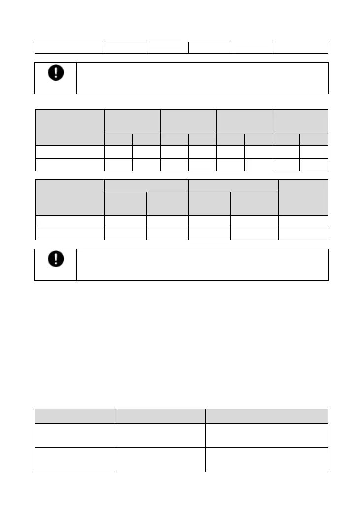
CAUTION
The above parameters are calculated under the STC (Standard Test
Condition)--module temperature 25℃, air mass1.5, irradiance 1000W/m2.)
Tracer1210/2210/3210/4210AN:
System voltage
36cell
Voc< 23V
48cell
Voc< 31V
54cell
Voc< 34V
60cell
Voc< 38V
Max.
Best
Max.
Best
Max.
Best
Max.
Best
12V
4
2
2
1
2
1
2
1
24V
4
3
2
2
2
2
2
2
System voltage
72cell Voc< 46V
96cell Voc< 62V
Thin-Film
module
Voc> 80V
Max.
Best
Max.
Best
12V
2
1
1
1
1
24V
2
1
1
1
1
CAUTION
The above parameters are calculated under the STC (Standard Test
Condition)--module temperature 25℃, air mass1.5, irradiance 1000W/m2.)
2.3 Wire size
The wiring and installation methods conform to the national and local electrical code requirements.
PV wire size
The PV array's output current varies with size, connection method, and sunlight angle. Its ISC (short
circuit current) can calculate the minimum wire size. Please refer to the ISC value in the PV module's
specifications. When the PV modules are connected in series, the total ISC equals any PV module's ISC.
When the PV modules are connected in parallel, the total ISC equals the sum of the PV module's ISC.
The PV array's ISC must not exceed the controller's maximum PV input current. For max. PV input
current and max. PV wire size, please refer to the table below:
Model
Max. PV input current
Max. PV wire size
Tracer1206AN
Tracer1210AN
10A
4mm
2
/12AWG
Tracer2206AN
Tracer2210AN
20A
6mm
2
/10AWG
Bekijk gratis de handleiding van EPEVER Tracer 4210AN, stel vragen en lees de antwoorden op veelvoorkomende problemen, of gebruik onze assistent om sneller informatie in de handleiding te vinden of uitleg te krijgen over specifieke functies.
Productinformatie
| Merk | EPEVER |
| Model | Tracer 4210AN |
| Categorie | Niet gecategoriseerd |
| Taal | Nederlands |
| Grootte | 4262 MB |


