Envertec EVT2000 handleiding
Handleiding
Je bekijkt pagina 19 van 22
33 34
Post-Startup LED Indications:
Check LED status to confirm the present situation.
Flashing Green:
It indicates normal operation.
Flashing Red:
1. If a red light flashes every 2 or 3 seconds, it indicates that the microinverter
is waiting for the sun or preparing to produce energy.
2. If the red light flashes continuously, it indicates that the microinverter is not
operating normally. The microinverter does not detect that the utility grid is
within operable voltage/frequency range. The microinverter cannot produce
power until this is solved.
7.2 Troubleshoot an Inoperable Microinverter
To troubleshoot an inoperable microinverter, follow the steps in the order
shown below.
WARNING: Be aware that only qualified personnel should troubleshoot the PV
array or the Envertech microinverter.
Best Practice: Please do not disconnect the DC connection while the system is
working. Ensure that no current is flowing in the DC wires prior to
disconnecting. If necessary, use an opaque to cover the PV module prior to
disconnecting the PV module. Always disconnect AC power before
disconnecting the PV module from the Envertech microinverter. Disconnecting
AC connectors of the microinverters is also a means of cutting off AC power.
WARNING: The AC and DC connectors on the cabling are rated as a
disconnecting point only when used with an Envertech microinverter.
WARNING: Envertech microinverters are powered by DC power from the PV
modules. Please disconnect and reconnect DC power to check the LED blinks 1
minute after DC is applied.
1. Make sure AC breakers are on.
2. Check the connection to the utility grid and verify that the grid voltage is
within the allowable ranges shown in the Technical Data section.
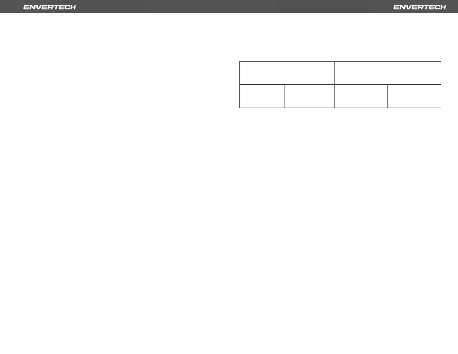
3. Verify that AC voltage at all solar power circuit breakers of the load centers
is within the ranges shown in the following table.
4. Verify that AC line voltage at the junction box for each AC branch circuit is
within the ranges required by local grid standards.
5. Confirm if the microinverter side is connected to the grid by measuring the
voltage from AC line to line and line to neutral.
6. Visually check if AC branch circuit connection is correctly done. Reinstall if
necessary. Check also for damage, such as rodent damage.
7. Make sure that all circuit breakers are off.
8. Disconnect and re-connect the PV modules’ DC connectors with
microinverters. The LED status of each microinverter will blink green to
indicate normal start-up operation soon after DC power is applied (less than
one minute).
9. Attach an ammeter clamp to one conducting wire of the DC cables from the
PV module to measure the microinverter’s current. This will be under 1 Amp if
AC is disconnected.
10. Check the DC connection between the microinverter and the PV module.
The connection may need to be tightened or reseated. If the connection is
worn out or damaged, it needs replacement.
11. Verify with your utility company that grid frequency is within the regulated
range.
7.3 Disconnect Microinverters from PV Modules
If your problems are still unsolved with the steps above, please contact
Envertech tech support through www.envertec.com. If Envertech approves the
replacement, please take off the microinverter according to the following
instructions. In order to ensure the disconnection between the microinverter
Single-Phase 230 VAC
Three-Phase 230 VAC
L to N
189 to 260VAC
L1 to L2 to L3
310 to 460VAC
Bekijk gratis de handleiding van Envertec EVT2000, stel vragen en lees de antwoorden op veelvoorkomende problemen, of gebruik onze assistent om sneller informatie in de handleiding te vinden of uitleg te krijgen over specifieke functies.
Productinformatie
| Merk | Envertec |
| Model | EVT2000 |
| Categorie | Niet gecategoriseerd |
| Taal | Nederlands |
| Grootte | 6025 MB |


