Elation PARAGON LT handleiding
Handleiding
Je bekijkt pagina 5 van 7
5
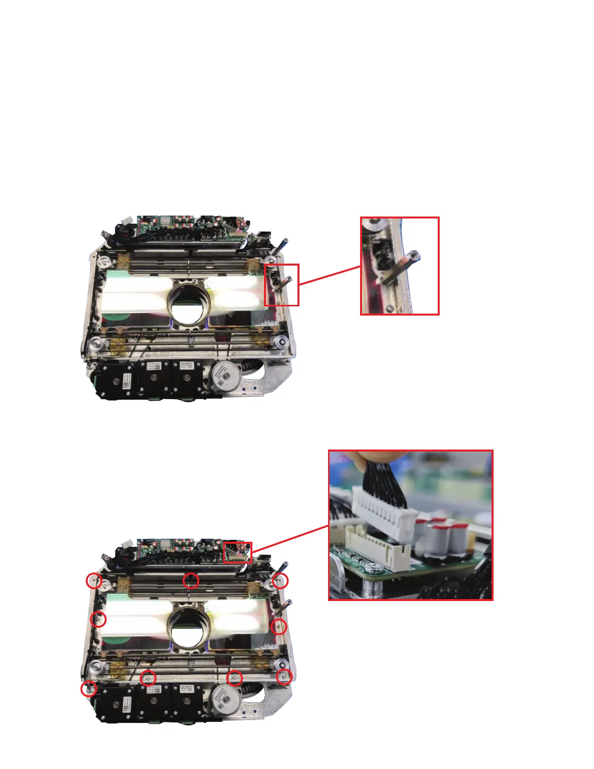
Step 5: Orient the RGB Module with its circuit board facing upwards. Lower the RGB module onto
the Gobo module, making sure to align the hexagonal hole on the right edge of the RGB module
with the hexagonal shaft on the right side of the base plate of the Gobo module, as shown in the
upper image. If installed in the correct orientation, the circuit boards of both the RGB module
and Gobo module should be side by side. Secure in place by re-installing the fasteners from the
reinforcing plate in the locations shown in the lower image below. If necessary, slide the RGB
ags towards the middle of the module to improve access to the fastener locations. Connect the
electrical connector coming from the RGB module to the matching plug in on the right side of
circuit board, as shown in the lower image below.
Hex alignment hole
aligned with hex shaft
Connect RGB Module electrical
connector to plug on the right
side of the main circuit board
Bekijk gratis de handleiding van Elation PARAGON LT, stel vragen en lees de antwoorden op veelvoorkomende problemen, of gebruik onze assistent om sneller informatie in de handleiding te vinden of uitleg te krijgen over specifieke functies.
Productinformatie
| Merk | Elation |
| Model | PARAGON LT |
| Categorie | Verlichting |
| Taal | Nederlands |
| Grootte | 4436 MB |


