EBERLE MWU 80 handleiding
Handleiding
Je bekijkt pagina 2 van 2
5
6
7
8
9
1
2
3
4
MWU 260
MWU 80
cos φ ≥ 0.95
M M
HAL.230V
K
M M
AC12
250V / 10A
DC14
24V / 2A
AC1
250V / 16A
AC13
250V / 6A
AC2
250V / 5A
AC14
250V / 6A
AC3
250V / 3A
AC15
250V / 6A
AC5b
800W
DC5
24V / 4A
AC6a
x
DC12
24V / 16A
AC7b
250V / 3A
DC13
24V / 2A
DC1
24V / 16A
DC3
24V / 6A
MWU 260 MWU 80
t
D
MWU 260
A1
15
R
Un
16
A2
18
~
+
~
-
RESET
MWU 80
RESET
U
EBERLE
Klingenhofstrasse 71
90411 Nürnberg
Tel.: +49 911 5693 – 0
Fax: +49 911 5693 536
E-Mail: info@eberle.de
Web: www.eberle.de
RESET
Un
Umax
t
Umin
LED
Latch
d
d
Un
Umax
t
Umin
t<t
d
Un
Umax
t
Umin
t<t
d
Un
Umax
t
Umin
t<t
d
O2 U2
O1 U1
UL
OL U3
Un
Umax
t
Umin
t<t
d
RESET
t
d
Un
Umax
Umin
Latch
Un
Umax
t
Imin
t
LED
<t
d
LEDLED
LED LED
LED
d
W
WL
Un
Umax
t
Umin
t
d
Un
Umax
Umin
Latch
t
d
LED
LED
d
Multifunction voltage monitoring relays in 1P - AC/DC
Characteristics
Description
Type of load
Contact material
AgNi, 16A
Type of load
Contact material
AgNi, 16A
AC5a
uncompensated
230V / 3A (690VA)
AC5a
compensated
x
EN
function U3
fault
state
function
RESET
time delay to
fault state
OK
state
OK
state
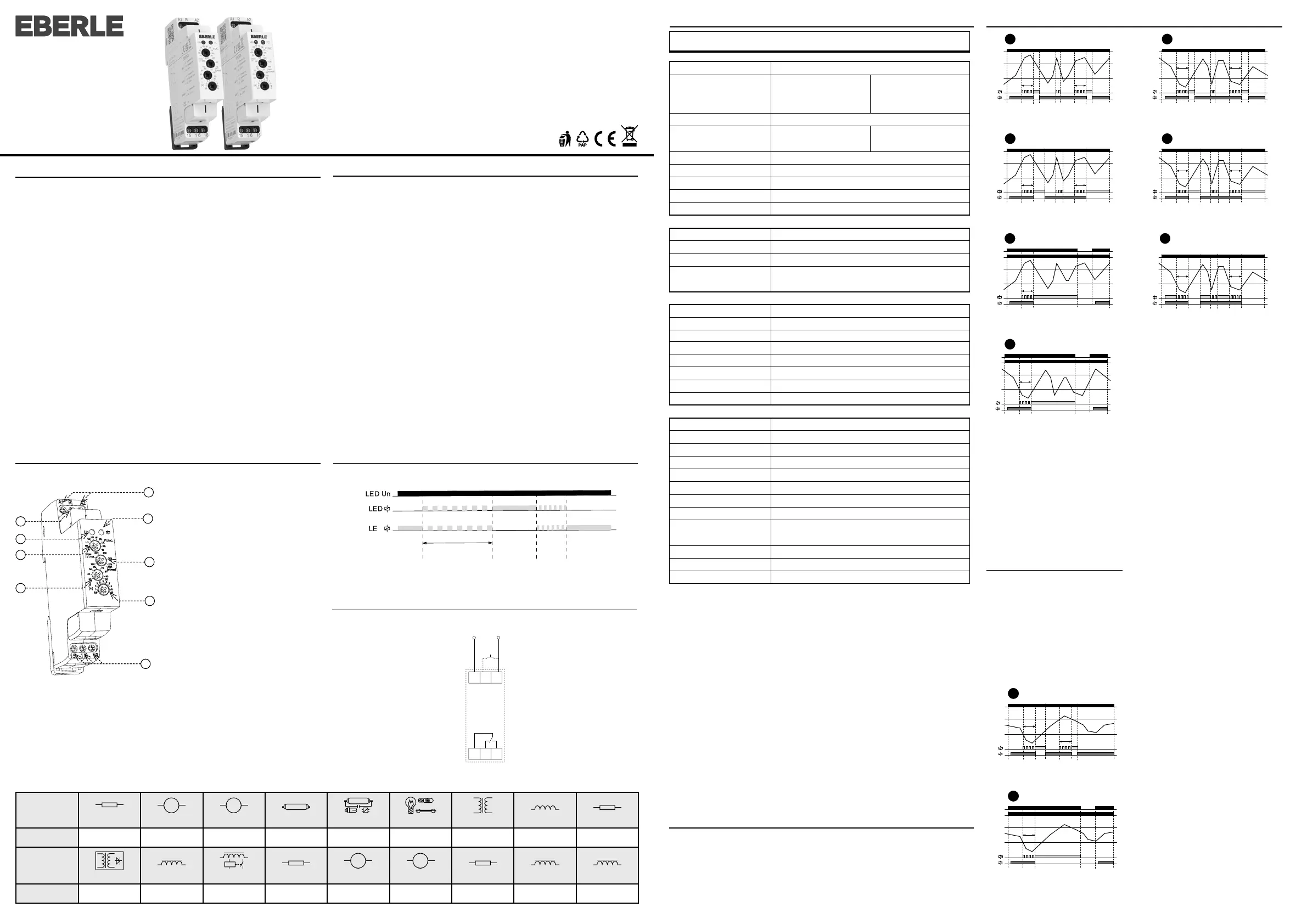
Indication of operating states
• It is used to monitor the value of alternating or direct voltage in 1-phase circuits.
• Supply voltage from monitored voltage.
• Monitors voltage exceeding the upper voltage level (Umax) and falling below the
lower voltage level (Umin) – according to the selected function.
• Smooth adjustment of both voltage levels – the lower level Umin is set in % of the
upper level Umax.
• Adjustable time delay (to eliminate short-term voltage drops and spikes).
• Option to select functions with fault state memory (Latch).
• The fault state memory can be reseted by the control input (R).
• Measures true root mean square value of the voltage - TRUE RMS.
1. Control input terminal (R)
2. Indication of supply/monitored
voltage
3. Function settings
4. Lower level setting (Umin)
5. Supply/monitored voltage terminals
(A1-A2)
6. Indication of operating states
7. Upper level setting (Umax)
8. Time delay setting
9. Output contact 1 (15-16-18)
Warning
This device is constructed for connection in 1-phase network or direct circuit (according
to the type, voltage ranges must be respected) and must be installed according to norms
valid in the state of an application. Installation, connection, setting and servicing must be
carried out by quali ed electrician sta only, which have perfectly understood the instruc-
tions and functions. This device contains protection against overvoltage peaks and dis-
turbing impulses in the power supply network. For the correct function of the protection
of this device, there must be suitable protections of higher degrees (A,B,C) installed in front
of them and according to the standards, interference of switching devices must be secure-
ly eliminated (contactors, motors, inductive loads, etc.). Before installation, make sure that
the device is de-energized and the main switch is in the “OFF” position. Do not install the
device to sources of excessive electromagnetic interference . Ensure correct installation
by perfect air circulation so that during continuous operation and a higher ambient tem-
perature, the device does not exceed the maximum allowed operating temperature. For
installation and setting use a screwdriver with a width of approx 2 mm. Keep in mind that
this is a fully electronic device and approach accordingly with the installation. Non -prob-
lematic function of the device is also dependent on the previous method of transportation,
storage, and handling. In case of any signs of damage, deformation, malfunction, or miss-
ing parts, don‘t install this device and claim it at the dealer. The product must be treated as
electronic waste at the end of its life.
Connection
Technical parameters
OVER:
If the value of the monitored voltage is lower than the
set upper level „Umax“, the output contact is closed.
If the „Umax“ is exceeded, the output contact will
opens after the set delay (fault state).
If the voltage falls below the xed hysteresis (O1
function) or the set lower level „Umin“ (O2 function),
the output contact will closes again.
If the OL function (OVER + Latch) is selected, when
the upper voltage level „Umax“ is exceeded, the
output contact remains open even when the voltage
returns from the fault state.
Fault memory reset can be done in three ways:
• Short-term interruption of supply voltage
• Using the control input (R)
• By setting the function switch to position R
(RESET) or any function without memory fault
The RESET state lasts for 3 s after switching the
function switch from the R position to a function
with a memory fault (UL, OL, WL).
When moving to any other function from the R
position, this delay does not apply.
UNDER:
If the value of the monitored voltage is higher than
the set lower level „Umin“, the output contact is
closed. When the voltage drops below the „Umin“,
output contact opens after the set delay (fault
state).
If the voltage exceeds the xed hysteresis (function
U1) or the set upper level „Umax“ (function U2, U3),
the output contact closes again.
If the UL function (UNDER + Latch) is selected,
when the voltage drops below the lower level
„Umin“, the output contact remains open even
when returning from the fault state. Fault memory
reset can be done as in the previous case.
WINDOW:
If the value of the monitored voltage is lower than
upper level „Umax“ and at the same time higher
than lower level „Umin“, the output contact in
closed. If the „Umax“ is exceeded or drops below
the „Umin“, output contact opens after the set
delay (fault state).
To return from the fault state, a xed hysteresis is
applied.
If the WL function (WINDOW + Latch) is selected,
the fault state is again stored in memory and
output contact stays open, even when returning
from the fault state. Fault memory reset can be
done as in the previous cases.
OVER (hysteresis to Umin)
UNDER (hysteresis to Umax)
WINDOW (hysteresis 5%)
OVER (hysteresis 5%)
UNDER (hysteresis 5%)
UNDER + Latch
OVER + Latch UNDER (hysteresis to Umax)
WINDOW + Latch
Supply and measuring
Supply/monitored terminals:
Supply/monitored voltage:
Consumption (max.):
Upper level setting (Umax):
Lower level setting (Umin):
Max. permanent voltage:
Peak overload (1 s):
Time delay (d):
Time delay (t):
Accuracy
Setting accuracy (mech.):
Repeat accuracy:
Temperature dependency:
Hysteresis
(fault to OK):
Output
Contact type:
Contact material:
Current rating:
Breaking capacity:
Switching voltage:
Power dissipation (max.):
Mechanical life:
Electrical life (AC1):
Other information
Operating temperature:
Storage temperature:
Dielectric strength:
Operating position:
Mounting:
Protection degree:
Overvoltage category:
Pollution degree:
Cross-wire section – solid/
stranded with ferrule (mm
2
):
Dimensions:
Weight:
Standards:
A1-A 2
AC/DC AC/DC
48 – 276 V 24 – 150 V
(AC 50-60 Hz) (AC 50-60 Hz)
2.5 VA/0.55 W
AC/DC AC/DC
160 – 276 V 80 – 150 V
30 – 95 %Umax
AC/DC 276 V
AC/DC 290 V
300 ms
adjustable, 0.5 – 10 s
5 % – mechanical setting
< 1 %
< 0.1 %/°C
5 % (functions O1, U1, W)
Umax – Umin (functions O2, U2, U3)
1×
changeover
AgNi
16 A/AC1
4000 VA/AC1, 384 W/DC1
250 V AC/24 V DC
1.2 W
10.000.000 ops.
100.000 ops.
–20 .. +55 °C
–30 .. +70 °C
AC 4 kV (supply – output)
any
DIN rail EN 60715
IP40 front panel / IP20 terminals
III.
2
max. 1× 2.5, 2× 1.5/
max. 1× 2.5 (AWG 14)
90 × 17.6 × 64 mm (3.5˝ × 0.7˝ × 2.5˝)
60 g (2.11 oz)
EN 60255-1, EN 60255-26, EN 60255-27
Functions
Bekijk gratis de handleiding van EBERLE MWU 80, stel vragen en lees de antwoorden op veelvoorkomende problemen, of gebruik onze assistent om sneller informatie in de handleiding te vinden of uitleg te krijgen over specifieke functies.
Productinformatie
| Merk | EBERLE |
| Model | MWU 80 |
| Categorie | Niet gecategoriseerd |
| Taal | Nederlands |
| Grootte | 985 MB |