Dual KA 12 L handleiding
Handleiding
Je bekijkt pagina 4 van 18
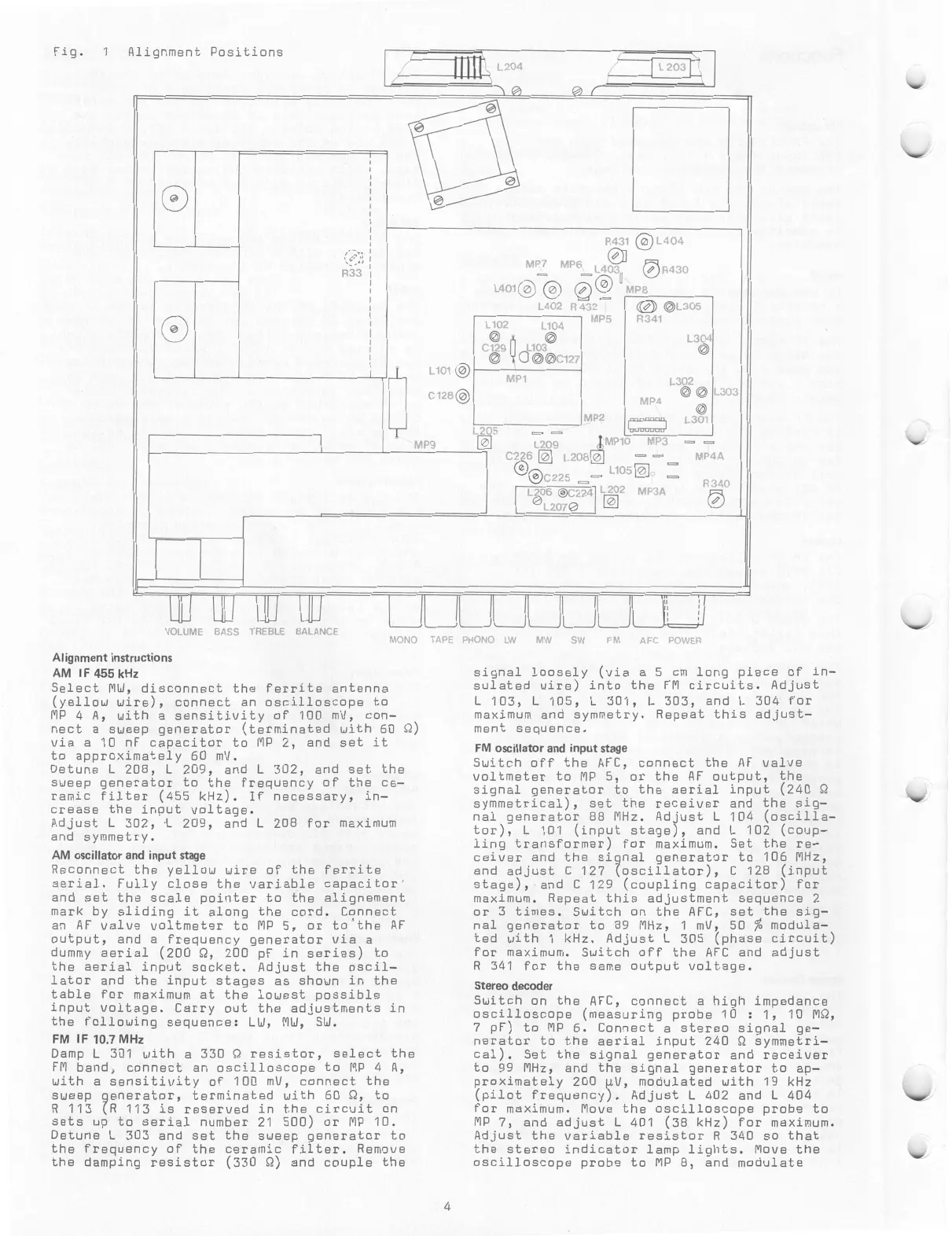
Fig.
1
Alignment
Positions
L
20
,
1
L
203
R33
()
r
Lim
®
C
128
®
MP9
R431
L404
MP7
MP6
L403
6
R430
L401®®
c9
MP8
L402
R432
MP5
L102
0
C129
L104
0
L103
0
00C127
MP1
LAD5
—
—
L209
C226
E
L208
C
bC225
L202
MP3A=='
L105
E,
MP2
L206
®C224
0
L
2070
©L305
R341
MP4
L304
0
L302
00
0
L301
L303
MP10
MP3
—
MP4A
R340
VOLUME
BASS
TRFBLE
BALANCE
MONO
TAPE
PHONO
LW
MW
SW
Alignment
instructions
AM
IF
455
kHz
Select
MW,
disconnect
the
ferrite
antenna
(yellow
wire),
connect
an
oscilloscope
to
MP
4
A,
with
a
sensitivity
of
100
mV,
con—
nect
a
sweep
generator
(terminated
with
60
Q)
via
a
10
nF
capacitor
to
MP
2,
and
set
it
to
approximately
60
mV.
Detune
L
208,
L
209,
and
L
302,
and
set
the
sweep
generator
to
the
frequency
of
the
ce—
ramic
filter
(455
kHz).
If
necessary,
in—
crease
the
input
voltage.
Adjust
L
302,
L
209,
and
L
208
for
maximum
and
symmetry.
AM
oscillator
and
input
stage
Reconnect
the
yellow
wire
o
aerial.
Fully
close
the
var
and
set
the
scale
pointer
t
mark
by
sliding
it
along
th
an
AF
valve
voltmeter
to
MP
output,
and
a
frequency
gen
dummy
aerial
(200
Q,
200
pF
the
aerial
input
socket.
Ad
lator
and
the
input
stages
table
for
maximum
at
the
lo
input
voltage.
Carry
out
th
the
following
sequence:
LW,
f
the
ferrite
iable
capacitor'
o
the
alignement
e
cord.
Connect
5,
or
to'the
AF
erator
via
a
in
series)
to
just
the
oscil—
as
shown
in
the
west
possible
e
adjustments
in
MW,
SW.
FM
IF
10.7
MHz
Damp
L
301
with
a
330
Q
resistor,
select
the
FM
band,
connect
an
oscilloscope
to
MP
4
A,
with
a
sensitivity
of
100
mV,
connect
the
sweep
generator,
terminated
with
60
Q
v
to
R
113
(R
113
is
reserved
in
the
circuit
on
sets
up
to
serial
number
21
500)
or
MP
10.
Detune
L
303
and
set
the
sweep
generator
to
the
frequency
of
the
ceramic
filter.
Remove
the
damping
resistor
(330
Q)
and
couple
the
LI
FM
AFC
POWER
signal
loosely
(via
a
5
cm
long
piece
of
in—
sulated
wire)
into
the
FM
circuits.
Adjust
L
103,
L
105,
L
301,
L
303,
and
L
304
for
maximum
and
symmetry.
Repeat
this
adjust—
ment
sequence.
FM
oscillator
and
input
stage
Switch
off
the
AFC,
connect
the
AF
valve
voltmeter
to
MP
5,
or
the
AF
output,
the
signal
generator
to
the
aerial
input
(240
symmetrical),
set
the
receiver
and
the
sig—
nal
generator
88
MHz.
Adjust
L
104
(oscilla—
tor),
L
101
(input
stage),
and
L
102
(coup—
ling
transformer)
for
maximum.
Set
the
re—
ceiver
and
the
signal
generator
to
106
MHz,
and
adjust
C
127
(oscillator),
C
128
(input
stage),
and
C
129
(coupling
capacitor)
for
maximum.
Repeat
this
adjustment
sequence
2
or
3
times.
Switch
on
the
AFC,
set
the
sig—
nal
generator
to
89
MHz,
1
mV,
50
%
modula—
ted
with
1
kHz.
Adjust
L
305
(phase
circuit)
for
maximum.
Switch
off
the
AFC
and
adjust
R
341
for
the
same
output
voltage.
Stereo
decoder
Switch
on
the
AFC,
connect
a
high
impedance
oscilloscope
(measuring
probe
10
:
1,
10
MO,
7
pF)
to
MP
6.
Connect
a
stereo
signal
ge—
nerator
to
the
aerial
input
240
Q
symmetri—
cal).
Set
the
signal
generator
and
receiver
to
99
MHz,
and
the
signal
generator
to
ap—
proximately
200
4V,
modulated
with
19
kHz
(pilot
frequency).
Adjust
L
402
and
L
404
for
maximum.
Move
the
oscilloscope
probe
to
MP
7,
and
adjust
L
401
(38
kHz)
for
maximum.
Adjust
the
variable
resistor
R
340
so
that
the
stereo
indicator
lamp
lights.
Move
the
oscilloscope
probe
to
MP
8,
and
modulate
4
Bekijk gratis de handleiding van Dual KA 12 L, stel vragen en lees de antwoorden op veelvoorkomende problemen, of gebruik onze assistent om sneller informatie in de handleiding te vinden of uitleg te krijgen over specifieke functies.
Productinformatie
| Merk | Dual |
| Model | KA 12 L |
| Categorie | Niet gecategoriseerd |
| Taal | Nederlands |
| Grootte | 28356 MB |