Handleiding
Je bekijkt pagina 74 van 146
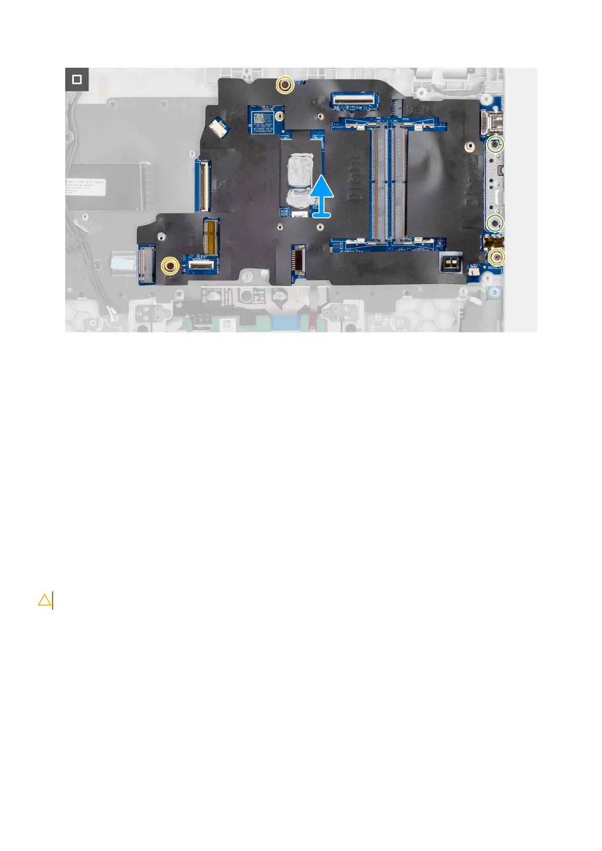
Figure 44. Removing the system board
Steps
1. Remove the two screws (M2.5x5) that secure the left display-hinge to the palm-rest assembly.
2. Lift the left display-hinge in an upward direction away from the system board.
3. Disconnect the following cables from the respective connectors on the system board:
● Display cable (EDP)
● Power-adapter port cable
● Speaker cable
● Touchpad cable
● I/O-board cable
● Fan cable
4. Remove the two screws (M2x5) that secure the Type-C module to the system board.
5. Remove the three screws (M2x3) that secure the system board to the palm-rest assembly.
6. Lift the system board off the palm-rest assembly.
Installing the system board
CAUTION: The information in this installation section is intended for authorized service technicians only.
Prerequisites
If you are replacing a component, remove the existing component before performing the installation procedure.
About this task
The following image indicates the connectors on your system board.
74
Removing and installing Field Replaceable Units (FRUs)
Bekijk gratis de handleiding van Dell Pro 14 PC14255, stel vragen en lees de antwoorden op veelvoorkomende problemen, of gebruik onze assistent om sneller informatie in de handleiding te vinden of uitleg te krijgen over specifieke functies.
Productinformatie
| Merk | Dell |
| Model | Pro 14 PC14255 |
| Categorie | Laptop |
| Taal | Nederlands |
| Grootte | 54332 MB |


