Handleiding
Je bekijkt pagina 72 van 146
About this task
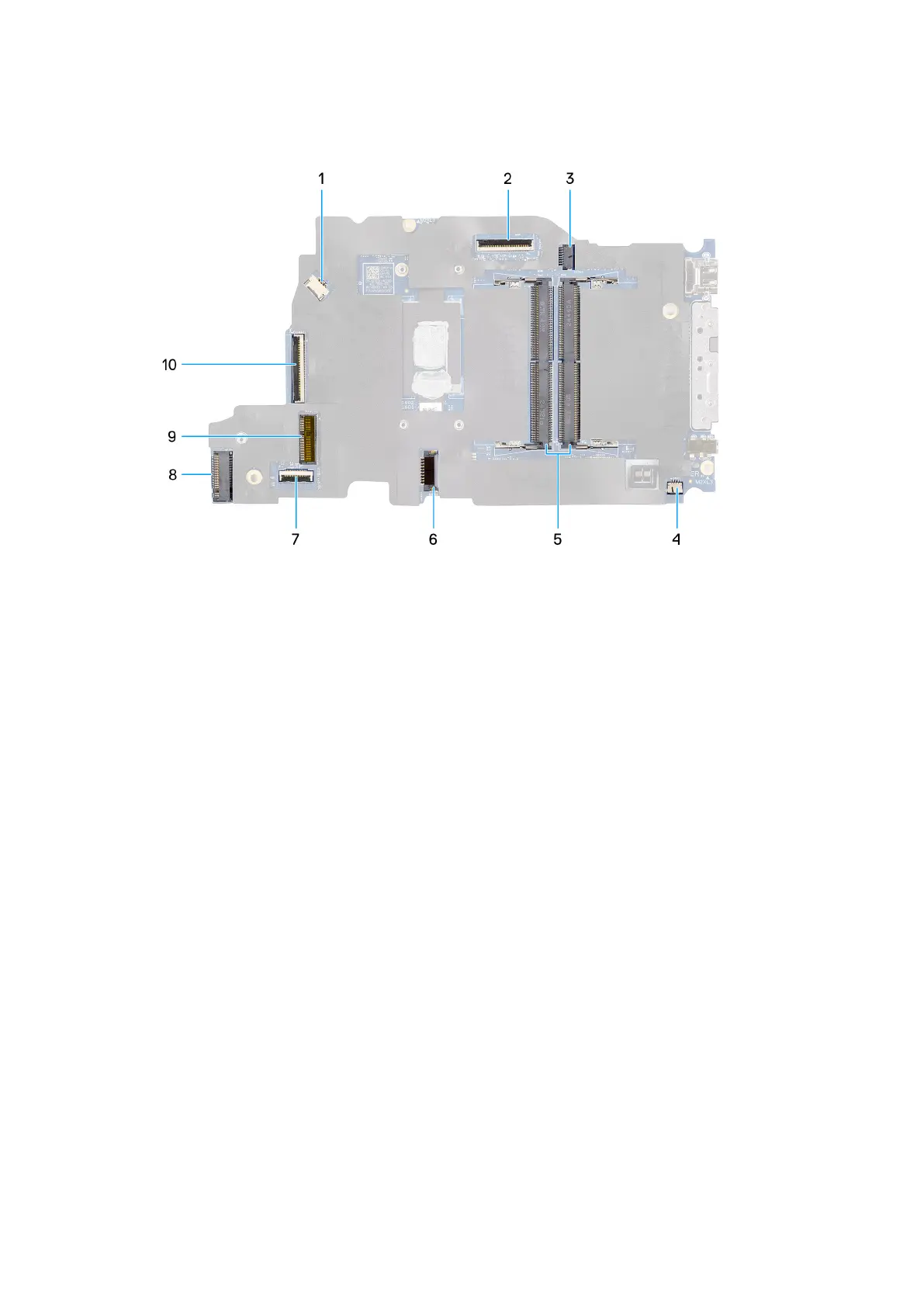
The following image indicates the connectors on your system board.
Figure 42. System-board connectors
1. Fan-cable connector (FAN1)
2. Display-cable connector (LCD1)
3. DC-in port connector (DCIN1)
4. Speaker-cable connector (SPK1)
5. Memory-module connectors (DM1 AND DM2)
6. Battery-cable connector (BATT1)
7. Touchpad-cable connector (TPAD1)
8. Wireless-card connector (WLAN1)
9. SSD slot
10. I/O-board cable connector (IO)
The following images indicate the location of the system board and provide a visual representation of the removal procedure.
72
Removing and installing Field Replaceable Units (FRUs)
Bekijk gratis de handleiding van Dell Pro 14 PC14255, stel vragen en lees de antwoorden op veelvoorkomende problemen, of gebruik onze assistent om sneller informatie in de handleiding te vinden of uitleg te krijgen over specifieke functies.
Productinformatie
| Merk | Dell |
| Model | Pro 14 PC14255 |
| Categorie | Laptop |
| Taal | Nederlands |
| Grootte | 54332 MB |


