Handleiding
Je bekijkt pagina 56 van 99
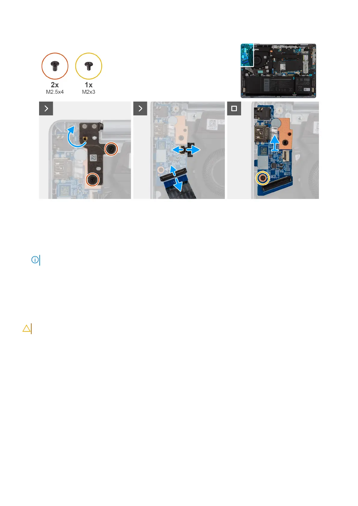
Figure 32. Removing the I/O board
Steps
1. Remove the two screws (M2.5x4) that secure the display-assembly hinge to the palm-rest and keyboard assembly.
2. Pry open the display-assembly hinge to a 90-degree angle.
3. Lift the latch and disconnect the fingerprint-reader cable from the connector on the I/O board.
NOTE: This step is applicable only to computers that are shipped with the optional power button with fingerprint reader.
4. Lift the latch and disconnect the I/O-board cable from the connector on the I/O board.
5. Remove the screw (M2x3) that secures the I/O board to the palm-rest and keyboard assembly.
6. Lift the I/O board off the palm-rest and keyboard assembly.
Installing the I/O board
CAUTION: The information in this section is intended for authorized service technicians only.
Prerequisites
If you are replacing a component, remove the existing component before performing the installation process.
About this task
The following image indicates the location of the I/O board and provides a visual representation of the installation procedure.
56
Removing and installing Field Replaceable Units (FRUs)
Bekijk gratis de handleiding van Dell 14 Plus DB14250, stel vragen en lees de antwoorden op veelvoorkomende problemen, of gebruik onze assistent om sneller informatie in de handleiding te vinden of uitleg te krijgen over specifieke functies.
Productinformatie
| Merk | Dell |
| Model | 14 Plus DB14250 |
| Categorie | Laptop |
| Taal | Nederlands |
| Grootte | 38915 MB |


