Dantherm HCV 700 handleiding
Handleiding
Je bekijkt pagina 23 van 60
23
INSTALLATION & SERVICE MANUAL FOR PROFESSIONALS
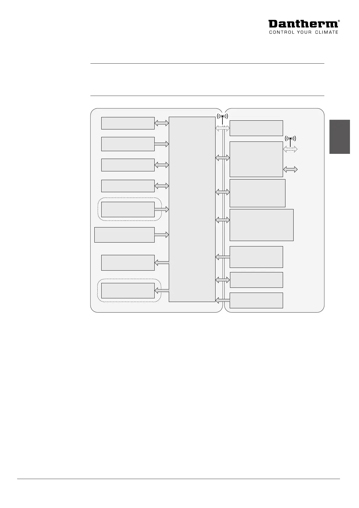
Product description: Electronic control
en
Electronic control
The main control system for the unit is located on the main PCB together with other outputs
and inputs.
The membrane panel with LED display is connected to the main PCB with a at cable.
This illustration shows the general architecture of the system control:
Externally connected items
HRC3 wireless
remote control
Ethernet router with
DHCP
HAC2 on MODBUS
Auxiliary box with
FPC (accessory)
HCP 10/11 on
MODBUS
(wired remote control)
USB service port
230 VAC input
Dantherm Main
controller PCB
Smart-
phone app
BMS
system
2 digital inputs
High/low fan speed,
etc.
Keypad with LED
Extract air fan
Supply air fan
Air quality demand
sensor (VOC)
Humidity
demand sensor (RH %)
Bypass 230 V
T1 - T4 Temperature
sensors
Accessories
HCV Unit
Preheater 230 VAC
Accessories
Fig. 8
Function
Illustration
Bekijk gratis de handleiding van Dantherm HCV 700, stel vragen en lees de antwoorden op veelvoorkomende problemen, of gebruik onze assistent om sneller informatie in de handleiding te vinden of uitleg te krijgen over specifieke functies.
Productinformatie
| Merk | Dantherm |
| Model | HCV 700 |
| Categorie | Niet gecategoriseerd |
| Taal | Nederlands |
| Grootte | 4620 MB |


