Danfoss VACON NXP handleiding
Handleiding
Je bekijkt pagina 76 van 178
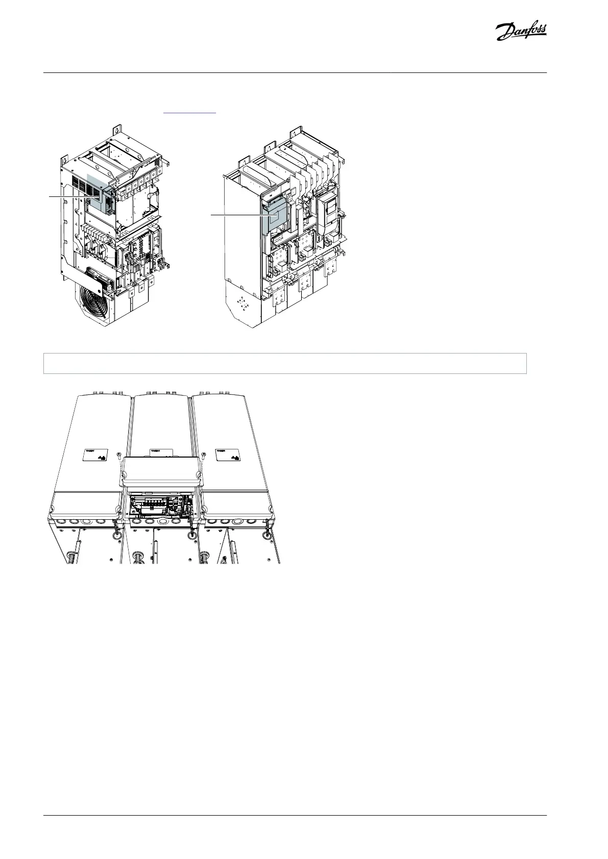
The control unit uses 24 V DC supplied from the ASIC board, which is on the left side of the power unit 1 in FR10–FR12, and in the
inverter unit in FR13–FR14 (see Illustration 62).
FR10
1
1
FR11
e30bk870.10
Illustration 61: Location of ASIC Board in FR10/FR11
1
ASIC board
e30bh595.10
Illustration 62: Location of ASIC Board in FR13–FR14
Each fiber optic cable has a number 1–8 and 11–18 (1–7 for FR10–FR11 and FR13) marked on the cable shield at both cable ends.
The list of the optic signals can be found in the following figures and table.
AQ468246143802en-000201 / DPD0088876 | Danfoss A/S © 2023.09
Control Unit
VACON® NXP IP00 Drive Modules
Operating Guide
Bekijk gratis de handleiding van Danfoss VACON NXP, stel vragen en lees de antwoorden op veelvoorkomende problemen, of gebruik onze assistent om sneller informatie in de handleiding te vinden of uitleg te krijgen over specifieke functies.
Productinformatie
| Merk | Danfoss |
| Model | VACON NXP |
| Categorie | Niet gecategoriseerd |
| Taal | Nederlands |
| Grootte | 20640 MB |


