Handleiding
Je bekijkt pagina 27 van 32
13 Glossary
Installer reference guide
27
RZQG71L9V1L + RZQG71~125L8Y1L + RZQG140L7Y1L
Split system air conditioners
4P473074-1A – 2019.04
12.3 Wiring diagram: Outdoor unit
The wiring diagram is delivered with the unit, located at the inside of
the service cover.
Notes for RZQG_V1:
1 Symbols (see legend).
2 Colours (see legend).
3 This wiring diagram applies only to the outdoor unit.
4 Refer to the wiring diagram sticker (on the back of the service
cover) for how to use the BS1~BS4 and DS1 switches.
5 When operating, do not short-circuit protective devices S1PH
and S1PL.
6 Refer to the service manual for instructions on how to set the
selector switches (DS1). The factory setting of all switches is
OFF.
7 Refer to the combination table and the option manual for how
to connect the wiring to X6A, X28A and X77A.
Notes for RZQG_Y1:
1 This wiring diagram applies only to the outdoor unit.
2 Refer to the combination table and the option manual for how
to connect the wiring to X6A, X28A and X77A.
3 Refer to the wiring diagram sticker (on the back of the service
cover) for how to use the BS1~BS4 and DS1 switches.
4 When operating, do not short-circuit protective device S1PH.
5 Refer to the service manual for instructions on how to set the
selector switches (DS1). The factory setting of all switches is
OFF.
6 Only for 71 class.
Legend for wiring diagrams:
A1P~A2P Printed circuit board
BS1~BS4 Push button switch
C1~C3 Capacitor
DS1 DIP switch
F1U~F8U
(RZQG71_V1)
▪ F1U, F2U: Fuse
▪ F6U: Fuse (T 3.15A / 250V)
▪ F7U, F8U: Fuse (F 1.0A / 250V)
F1U~F8U
(RZQG_Y1)
▪ F1U, F2U: Fuse (31.5A / 250V)
▪ F1U (A2P): Fuse (T 5.0A / 250V)
▪ F3U~F6U: Fuse (T 6.3A / 250V)
▪ F7U, F8U: Fuse (F 1.0A / 250V)
H1P~H7P Light-emitting diode (service monitor is orange)
HAP Light-emitting diode (service monitor is green)
K1M, K11M Magnetic contactor
K1R
(RZQG_V1)
Magnetic relay (Y1S)
K1R
(RZQG_Y1)
▪ K1R (A1P): Magnetic relay (Y1S)
▪ K1R (A2P): Magnetic relay
K2R
(RZQG71_V1)
Magnetic relay
K2R
(RZQG_Y1)
▪ K2R (A1P): Magnetic relay (E1H option)
▪ K2R (A2P): Magnetic relay
K10R, K13R~K15R Magnetic relay
L1R~L3R Reactor
M1C Motor (compressor)
M1F Motor (upper fan)
M2F Motor (lower fan)
PS Switching power supply
Q1DI Earth leakage circuit breaker (field supply)
R1~R6 Resistor
R1T Thermistor (air)
R2T Thermistor (discharge)
R3T Thermistor (suction)
R4T Thermistor (heat exchanger)
R5T Thermistor (heat exchanger middle)
R6T Thermistor (liquid)
R7T, R8T
(RZQG71_V1)
Thermistor (Positive Temperature Coefficient)
R10T
(RZQG_Y1)
Thermistor (fin)
RC Signal receiver circuit
S1PH High pressure switch
S1PL Low pressure switch
TC Signal transmission circuit
V1D~V4D Diode
V1R IGBT power module
V2R, V3R Diode module
V1T~V3T Insulated gate bipolar transistor (IGBT)
X6A Connector (option)
X1M Terminal strip
Y1E Electronic expansion valve
Y1S Solenoid valve (4‑way valve)
Z1C~Z6C Noise filter (ferrite core)
Z1F~Z6F Noise filter
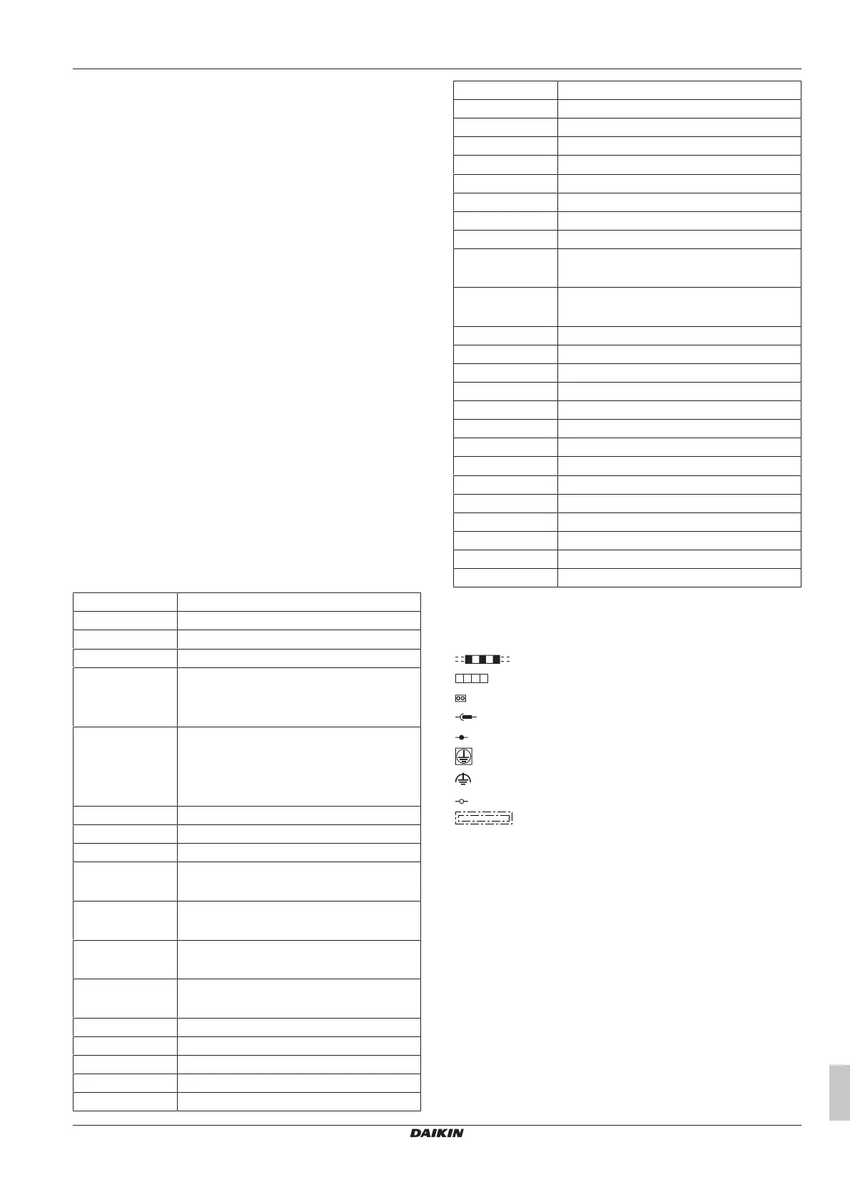
Symbols:
L Live
N Neutral
Field wiring
Terminal strip
Connector
Relay connector
Connection
Protective earth
Noiseless earth
Terminal
Option
Colours:
BLK Black
BLU Blue
BRN Brown
GRN Green
ORG Orange
RED Red
WHT White
YLW Yellow
13 Glossary
Dealer
Sales distributor for the product.
Bekijk gratis de handleiding van Daikin RZQG125L8Y1L, stel vragen en lees de antwoorden op veelvoorkomende problemen, of gebruik onze assistent om sneller informatie in de handleiding te vinden of uitleg te krijgen over specifieke functies.
Productinformatie
| Merk | Daikin |
| Model | RZQG125L8Y1L |
| Categorie | Airco |
| Taal | Nederlands |
| Grootte | 5226 MB |


