Daikin RYMA5A7Y1B handleiding
Handleiding
Je bekijkt pagina 31 van 64
15 Piping installation
Installation and operation manual
31
RYMA5+RXYA8~20A7Y1B
VRV 5 heat pump
4P739915-1C – 2024.10
a To indoor unit
b Oil collects to the outmost outdoor unit when the system
stops
NOT allowed (oil remains in piping)
Allowed
▪ If the piping length between the outdoor units exceeds 2m, create
a rise of 200 mm or more in the gas line within a length of 2 m
from the kit.
If Then
≤2m
a
b
≤2 m
>2m
a
≤2 m
≥200 mm
b
>2 m
a To indoor unit
b Piping between outdoor units
NOTICE
There are restrictions on the refrigerant pipe connection
order between outdoor units during installation in case of a
multiple outdoor unit system. Install according to following
restrictions. The capacities of outdoor units A and B must
fulfill the following restriction conditions: A≥B.
A B
a b
a To indoor units
b Outdoor unit multi connecting piping kit (first branch)
15.2 Connecting the refrigerant piping
15.2.1 Using the stop valve and service port
To handle the stop valve
Take the following guidelines into account:
▪ The gas, equalising and liquid stop valves are factory closed.
▪ Make sure to keep ONLY gas and liquid stop valves open during
operation. In case of multi outdoor unit system, also open
equalising stop valve.
▪ Do NOT apply excessive force to the stop valve. Doing so may
break the valve body.
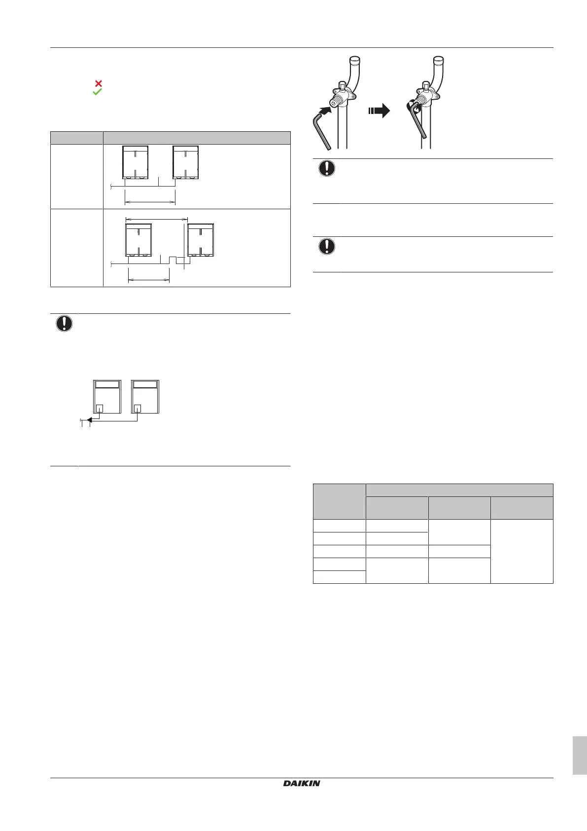
To open the stop valve
1 Remove the dust cap.
2 Insert a hexagon wrench into the stop valve.
3 FULLY turn the stop valve counterclockwise and tighten until
the correct tightening torque value is achieved (see "Tightening
torques"[431]).
NOTICE
Stop valves need to be opened on torque specified in this
manual. It is not allowed to turn valve "a quarter turn" back
when opening it.
4 Install the dust cap.
Result: The valve is now open.
NOTICE
Reinstall dust cap to prevent aging of O-ring and risk of
leakage.
To close the stop valve
1 Remove the stop valve cover.
2 Insert a hexagon wrench into the stop valve and turn the stop
valve clockwise.
3 When the stop valve cannot be turned any further, stop turning.
4 Install the stop valve cover.
Result: The valve is now closed.
To handle the service port
▪ Always use a charge hose equipped with a valve depressor pin,
since the service port is a Schrader type valve.
▪ After handling the service port, make sure to tighten the service
port cover securely. For the tightening torque, refer to the table
below.
▪ Check for refrigerant leaks after tightening the service port cover.
Tightening torques
Stop valve
size [mm]
Tightening torque [N•m]
(a)
Valve body Hexagonal
wrench
Service port
Ø9.5 5~7 4mm 10.7~14.7
Ø12.7 8~10
Ø15.9 14~16 6mm
Ø19.1 19~21 8mm
Ø25.4
(a)
When opening or closing.
15.2.2 To route the refrigerant piping
Installation of refrigerant piping is possible as front connection or
side connection (when taken out from the bottom) as shown in the
figure below.
Bekijk gratis de handleiding van Daikin RYMA5A7Y1B, stel vragen en lees de antwoorden op veelvoorkomende problemen, of gebruik onze assistent om sneller informatie in de handleiding te vinden of uitleg te krijgen over specifieke functies.
Productinformatie
| Merk | Daikin |
| Model | RYMA5A7Y1B |
| Categorie | Niet gecategoriseerd |
| Taal | Nederlands |
| Grootte | 11397 MB |


