Daikin RYMA5A7Y1B handleiding
Handleiding
Je bekijkt pagina 23 van 64
13 Special requirements for R32 units
Installation and operation manual
23
RYMA5+RXYA8~20A7Y1B
VRV 5 heat pump
4P739915-1C – 2024.10
For the upper opening:
▪ It is not an opening to the outside
▪ The opening cannot be closed
▪ The opening must be ≥0.006m² (50% of A
nvmin
)
▪ The bottom of the upper opening must be ≥1500 mm above the
floor
▪ The height of the opening is ≥20mm
Note: The requirement for the upper opening can be met by false
ceilings, ventilation ducts or similar arrangements that provide an
airflow path between the connected rooms.
NOTICE
Indoor units and the bottom of duct openings cannot be
installed lower than 1.8m from the lowest point of the floor,
except for floor standing indoor units (e.g. FXNA)
Example
The total amount of refrigerant in the VRV system is 20kg. The VRV
system has two indoor units which are installed in a space that does
not belong to the lowest underground floor of the building. The space
in which the indoor units are installed has a room area of 25m². An
adjacent room has a room area of 45 m² to which air circulation is
possible through a partition that meets one of the two requirements
in the above text. The safety measure chosen is Alarm + Natural
ventilation (based on the total amount of refrigerant and room area
from the graph for “All other floors”).
1 To apply the Alarm safety measure, see "13.4.2Alarm"[421].
2 In addition, apply the Natural ventilation safety measure: total
room areas of installed room and adjacent room where natural
ventilation can be made: 25m²+45m²=70m²
Result: Total refrigerant charge limit for the system determined
using the graph for natural ventilation is 23.6kg.
Total amount of refrigerant in the system (20kg) < Total refrigerant
charge limit (23.6kg), which means that the safety measure can be
applied.
13.4.4 Shut-off valves
In case shut-off valves are required as a safety measure, SV unit
which has shut-off valves needs to be installed to reduce the amount
of refrigerant leakage in to the room where the indoor unit is
installed.
For installation of the SV unit, refer to the installation and operation
manual delivered with the SV unit.
The maximum amount of charge limit and so the maximum capacity
class of indoor unit which is allowed to install in the room is
determined as below.
About the charge limit
The charge limit must be determined separately for each SV unit
branch pipe port.
This is possible because of the shut-off valves in the SV unit. The
maximum amount of refrigerant that can escape in case of a leak is
determined by the piping length and indoor heat exchanger size.
This is directly linked to the downstream indoor unit capacity of this
piping section.
In case a leak is detected in an indoor unit, the shut-off valves in the
SV unit of the respective port will close. The piping section with the
leak is now shut off from the rest of the system and the amount of
refrigerant that can leak is significantly reduced.
Note: When two branch pipe ports are combined in order to form a
single branch pipe port (e.g. FXMA200/250), they must be
considered as a single branch pipe port.
To determine the charge limit
Step1 – Determine the smallest area out of:
▪ Each of the rooms served by SV unit branch pipe port where an
indoor unit is installed
▪ Each of the rooms served by a ducted indoor unit installed in a
different room
The room area can be determined by projecting the walls, doors and
partitions to the floor and calculate the enclosed area. Spaces
connected by only false ceilings, ductwork, or similar connections
are NOT considered a single space.
The area of the smallest room calculated above is used in the next
step to determine the maximum allowable indoor capacity that can
be connected to that port.
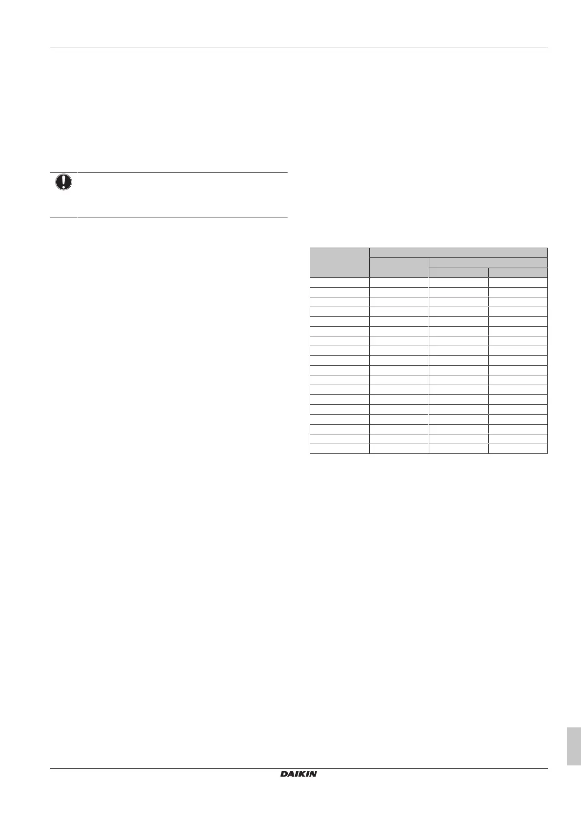
Step2 – Use the table below to determine the maximum total indoor
unit capacity (sum of all connected indoor units) that is allowed for a
single SV unit branch pipe port. In case a ducted indoor unit is
serving a different room than where it is installed, the restrictions of
the room area apply to both the indoor installation room and the
conditioned room separately. Supply and return air shall be directly
ducted to that room.
Area of installed/
conditioned room [m²]
Maximum total indoor unit capacity class
1 indoor unit per
branch pipe port
(a)
2~5 indoor units per branch pipe port
40m after 1
st
branch
(b)
90m after 1
st
branch
(c)
<5 — — —
5 10 — —
6 25 — —
7 32 — —
8 40 — —
9 71 — —
10 80 — —
11 80 20 —
12 80 25 —
13 80 32 —
14 80 32 —
15 125 40 —
20 200 50 40
25 250 71 71
30 250 125 125
35 250 200 200
40 250 200 200
≥45 250 250 250
(a)
One indoor unit connected to a single branch pipe port.
(b)
Two to five indoor units connected to a single branch pipe port,
40m after first refrigerant branch.
(c)
Two to five indoor units connected to a single branch pipe port,
90m after first refrigerant branch (size-up of liquid pipe, see
"15.1Preparing refrigerant piping"[428]).
Notes:
▪ The values in the table are under the assumption of worst case
indoor unit volume and 40 m piping between indoor and SV unit
and an installation height up to 2.2 m (bottom of indoor unit or
bottom of duct openings). In VRV Xpress it is possible to add
custom piping lengths, installation heights above 2.2 m and
custom indoor units which can lead to lower minimum room area
requirements.
▪ In case the capacity class allowed per branch pipe port is bigger
than 140, use SV1A unit or combine two ports while using
SV4~8A. For more information and installation of the SV unit,
please refer to the installation and operation manual delivered with
the SV unit.
▪ In case multiple indoor units are connected to the same branch
pipe port, the sum of the connected indoor unit capacity classes
needs to be equal or less than the value indicated in the table.
▪ In case indoor units connected to the same branch pipe port are
split over different rooms, the area of the smallest room needs to
be considered.
▪ Round down the derived values.
Step3 – The total indoor capacity connected to a branch pipe port
(or pair of branch pipe ports in case of FXMA200/250) MUST be
equal or less than the capacity limit that is derived from the table.
Bekijk gratis de handleiding van Daikin RYMA5A7Y1B, stel vragen en lees de antwoorden op veelvoorkomende problemen, of gebruik onze assistent om sneller informatie in de handleiding te vinden of uitleg te krijgen over specifieke functies.
Productinformatie
| Merk | Daikin |
| Model | RYMA5A7Y1B |
| Categorie | Niet gecategoriseerd |
| Taal | Nederlands |
| Grootte | 11397 MB |


