Daikin RXYQ10U7Y1B handleiding
Handleiding
Je bekijkt pagina 13 van 48
11 About the box
Installation and operation manual
13
RYYQ+RYMQ+RXYQ
VRV IV+ heat pump
4P546220-1F – 2023.01
NOTICE
Do NOT try to dismantle the system yourself: dismantling
of the system, treatment of the refrigerant, oil and other
parts MUST comply with applicable legislation. Units
MUST be treated at a specialised treatment facility for
reuse, recycling and recovery.
For the installer
11 About the box
11.1 About
is part of Daikin's wider commitment to reduce our
environmental footprint. With we want to create a circular
economy for refrigerants. One of the actions to achieve this, is the
reuse of reclaimed refrigerant in VRV units produced and sold in
Europe. For more information about the countries that are in scope,
visit: http://www.daikin.eu/loop-by-daikin.
11.2 To remove the accessories from
the outdoor unit
Make sure that all accessories are available in the unit.
a d
1× 1×
e
1×
3P328191-1
BE SURE TO FILL OUT THE BLANKS, WHICH ARE NEEDED FOR AFTER-SALE SERVICES.
REQUEST FOR THE INDICATION OF INSTALLATION INFORMATION
1. RECORD OF INDOOR UNIT MODEL AND INSTALLATION SITE
2. RECORD FOR SETTINGS (CONTENTS SEE INSTALLATION MANUAL)
SETTING
40
30
10
2019
9
29
3938
28
8
1817
7
27
3736
26
6
1615
5
25
3534
23 24
4321
INSTALLATION
MODELNAME
No.
12 13 14
504948474645
6059585756
64636261
11
2221
333231
44434241
5554535251
SITE
INSTALLATION
MODELNAME
No.
SITE
INSTALLATION
MODELNAME
No.
SITE
INSTALLATION
MODELNAME
No.
SITE
INSTALLATION
MODELNAME
No.
SITE
INSTALLATION
MODELNAME
No.
SITE
INSTALLATION
MODELNAME
No.
SITE
3. RECORD OF INSTALLATION DATE
6. AFTER EQUIPPING, PLEASE PUT IT ON THE BACK SIDE OF THE FRONT PLATE.
DAY MONTH YEAR
4. MODEL NAME 5. MANUFACTURING NUMBER
VALUE
REMARK DATE SETTING VALUE REMARK DATE
3P328192-1
3. FOR DETAILS CONCERNING PIPING SELECTION AND CALCULATION OR HOW TO OPERATE THE LEAK DETECTION FUNCTION, PLEASE REFER TO THE INSTALLATION MANUAL.
2. RECORD OF ADDITIONAL REFRIGERANT CHARGE AMOUNT AND RESULT OF LEAK CHECK OPERATION
REQUEST FOR THE INDICATION OF ADDITIONAL REFRIGERANT CHARGING AND LEAK DETECTION OPERATION RESULT
BE SURE TO FILL OUT THE BLANKS, WHICH ARE NEEDED FOR AFTER-SALE SERVICES.
1. CALCULATION OF ADDITIONAL REFRIGERANT CHARGING AMOUNT
4. AFTER FILLING IN THIS TABLE, PLEASE PUT IT ON THE SWITCH BOX COVER.
(m) x 0.18(m) x 0.37
kg
OUTDOOR
UNIT
(m) x 0.26
(m) x 0.12 (m) x 0.059
(m) x 0.022
ADDITIONAL CHARGING
AMOUNT
TOTAL LENGTH OF LIQUID
PIPE SIZE O22.2 x 0.37
TOTAL LENGTH OF LIQUID
PIPE SIZE O19.1 x 0.26
TOTAL LENGTH OF LIQUID
PIPE SIZE O15.9 x 0.18
TOTAL LENGTH OF LIQUID
PIPE SIZE O12.7 x 0.12
TOTAL LENGTH OF LIQUID
PIPE SIZE O9.5 x 0.059
TOTAL LENGTH OF LIQUID
PIPE SIZE O6.4 x 0.022
105%< CR < 130%
50%< CR < 105%
50%< CR < 70%
70%< CR < 85%
85%< CR < 105%
105%< CR < 130%
8HP
Total indoor unit
capacity connection
ratio (CR)
10-12HP
14-16HP
18-20HP
2.0
1.5
1.5
1.2
1.5
1
1
0.7
1.0
0.5
0.5
0.3
0.5
0
0
0
1.0
0.5
0.5
0.5
0.5
0
0
0
Total indoor unit capacity
when piping length <30m
Total indoor unit capacity
when piping length >30m
kg
1.3
1.1
0.9
RYYQ18-20
RYYQ14-16
RYYQ8~12
kg
ONLY FOR RYYQ8~20 MODELS
DATE
AMOUNT
CALCULATE THE ADDITIONAL REFRIGERANT CHARGING AMOUNT BASED ON THE FORMULA BELOW BEFORE CHARGING.
SHIPMENT (INDICATED ON THE MACHINE NAMEPLATE) AND THE ADDITIONAL AMOUNT SHOWN AS FOLLOWS :
WHEN RE-CHARGING TOTAL AMOUNT OF REFRIGERANT , CHARGE THE TOTAL OF THE AMOUNT CHARGED AT
RESULT LEAK CHECK
DATE
AMOUNT
RESULT LEAK CHECK
DATE
AMOUNT
RESULT LEAK CHECK
DATE
AMOUNT
RESULT LEAK CHECK
c
1×
b
1×
f g
1×1×
a General safety precautions
b Installation manual and operation manual
c Additional refrigerant charge label
d Installation information sticker
e Fluorinated greenhouse gases label
f Multilingual fluorinated greenhouse gases label
g Piping accessory bag
11.3 Accessory pipes: Diameters
Accessory pipes (mm) HP Øa Øb
Gas pipe
▪ Front connection
ID Øa
ID Øb
▪ Bottom connection
ID Øa
OD Øb
8 25.4 19.1
10 22.2
12 28.6
14
16
18
20
Accessory pipes (mm) HP Øa Øb
Liquid pipe
▪ Front connection
ID Øb
ID Øa
▪ Bottom connection
ID Øb
ID Øa
8 9.5
10
12 9.5 12.7
14 12.7
16
18 12.7 15.9
20
Equaliser pipe
(a)
▪ Front connection
ID Øa
ID Øb
▪ Bottom connection
ID Øa
OD Øb
8 19.1
10
12 19.1 22.2
14
16
18 25.4 28.6
20
(a) Only for RYMQ models.
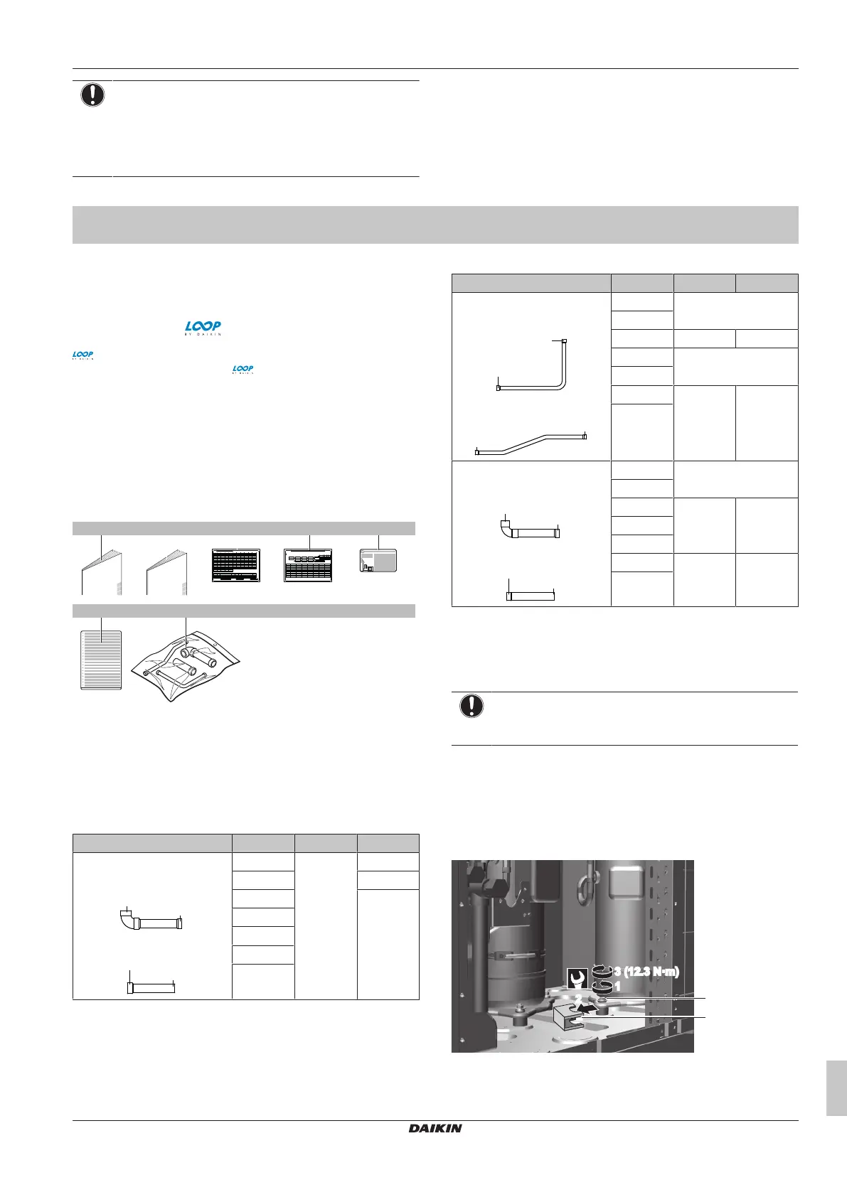
11.4 To remove the transportation stay
Only for 14~20 HP
NOTICE
If the unit is operated with the transportation stay attached,
abnormal vibration or noise may be generated.
The transportation stay installed over the compressor leg for
protecting the unit during transport must be removed. Proceed as
shown in the figure and procedure below.
1 Slightly loosen the fixing nut.
2 Remove the transportation stay as shown in the figure below.
3 Tighten the fixing nut again.
1
3 (12.3 N·m)
2
1
3 (12.3 N·m)
2
a
b
a Fixing nut
b Transportation stay
Bekijk gratis de handleiding van Daikin RXYQ10U7Y1B, stel vragen en lees de antwoorden op veelvoorkomende problemen, of gebruik onze assistent om sneller informatie in de handleiding te vinden of uitleg te krijgen over specifieke functies.
Productinformatie
| Merk | Daikin |
| Model | RXYQ10U7Y1B |
| Categorie | Niet gecategoriseerd |
| Taal | Nederlands |
| Grootte | 8429 MB |


