Daikin RXYLQ42T7Y1B handleiding
Handleiding
Je bekijkt pagina 25 van 40
15 Electrical installation
Installation and operation manual
25
RXMLQ8 + RXYLQ10~14T7Y1B*
VRV IV system air conditioner
4P543426-1C – 2025.01
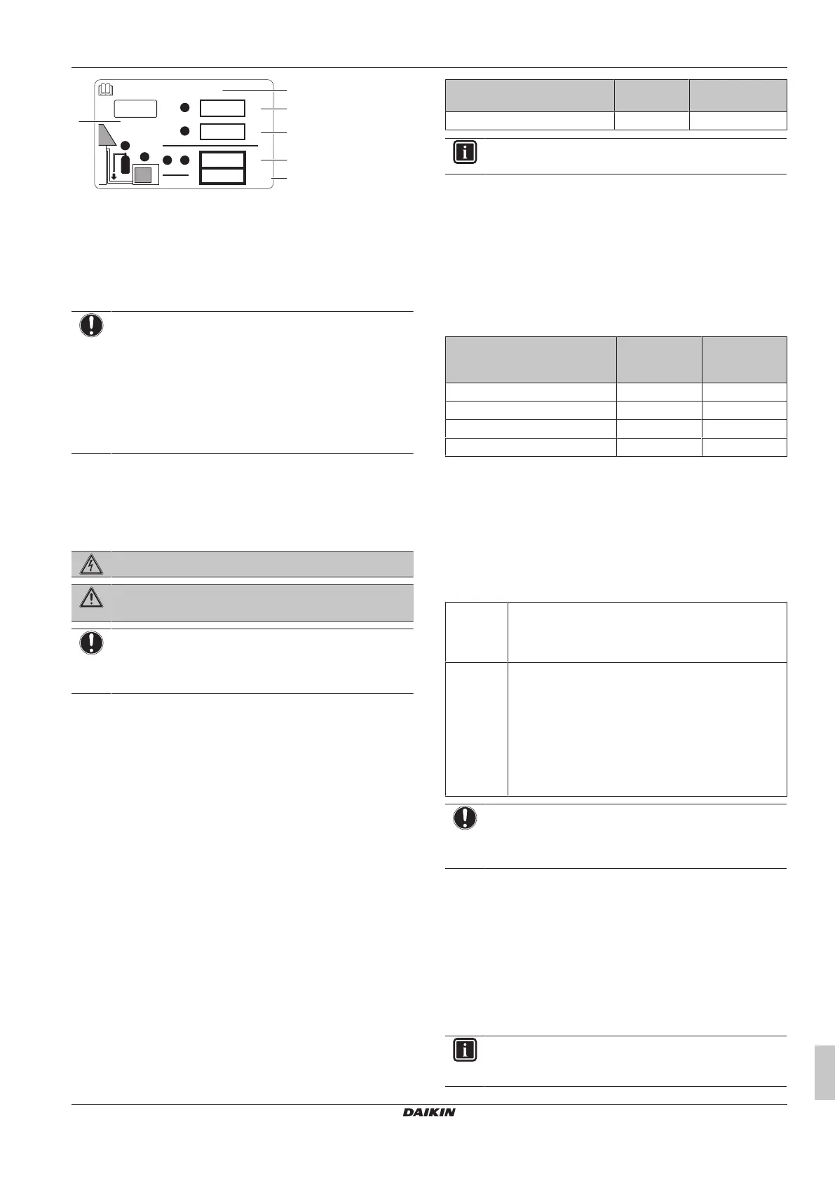
b
Contains fluorinated greenhouse gases
2
1
1
1
2
2
kg
tCO
2
eq
GWP × kg
1000
=
=
+
kg
=
kg
=
GWP: XXX
RXXX
a
f
c
d
e
a If a multilingual fluorinated greenhouse gases label is
delivered with the unit (see accessories), peel off the
applicable language and stick it on top of a.
b Factory refrigerant charge: see unit name plate
c Additional refrigerant amount charged
d Total refrigerant charge
e Quantity of fluorinated greenhouse gases of the total
refrigerant charge expressed as tonnes CO
2
equivalent.
f GWP = Global Warming Potential
NOTICE
Applicable legislation on fluorinated greenhouse gases
requires that the refrigerant charge of the unit is indicated
both in weight and CO
2
equivalent.
Formula to calculate the quantity in CO
2
equivalent
tonnes: GWP value of the refrigerant × total refrigerant
charge [in kg] / 1000
Use the GWP value mentioned on the refrigerant charge
label.
2 Fix the label on the inside of the outdoor unit near the gas and
liquid stop valves.
15 Electrical installation
DANGER: RISK OF ELECTROCUTION
WARNING
ALWAYS use multicore cable for power supply cables.
NOTICE
This is a class A product. In a domestic environment this
product may cause radio interference in which case the
user may be required to take adequate measures.
15.1 About electrical compliance
This equipment complies with:
▪ EN/IEC 61000‑3‑11
provided that the system impedance Z
sys
is
less than or equal to Z
max
at the interface point between the user's
supply and the public system.
▪ EN/IEC 61000‑3‑11 = European/International Technical
Standard setting the limits for voltage changes, voltage
fluctuations and flicker in public low-voltage supply systems for
equipment with rated current ≤75A.
▪ It is the responsibility of the installer or user of the equipment to
ensure, by consultation with the distribution network operator if
necessary, that the equipment is connected ONLY to a supply
with a system impedance Z
sys
less than or equal to Z
max
.
▪ EN/IEC 61000‑3‑12 provided that the short-circuit power S
sc
is
greater than or equal to the minimum S
sc
value at the interface
point between the user's supply and the public system.
▪ EN/IEC 61000‑3‑12 = European/International Technical
Standard setting the limits for harmonic currents produced by
equipment connected to public low-voltage systems with input
current >16A and ≤75A per phase.
▪ It is the responsibility of the installer or user of the equipment to
ensure, by consultation with the distribution network operator if
necessary, that the equipment is connected ONLY to a supply
with a short-circuit power S
sc
greater than or equal to the
minimum S
sc
value.
Model Z
max
(Ω) Minimum S
sc
value (kVA)
RXMLQ8 + RXYLQ10~14 — 5638.32
INFORMATION
Multi units are standard combinations.
15.2 Safety device requirements
The power supply must be protected with the required safety
devices, i.e. a main switch, a slow blow fuse on each phase and an
earth leakage protector in accordance with the applicable legislation.
For standard combinations
Selection and sizing of the wiring should be done in accordance with
the applicable legislation based on the information mentioned in the
table below.
Model Minimum
circuit
ampacity
Recommended
fuses
RXMLQ8 16.1A 20A
RXYLQ10 22.0A 25A
RXYLQ12 24.0A 32A
RXYLQ14 27.0A 32A
For all models:
▪ Phase and frequency: 3N~50Hz
▪ Voltage: 380~415V
▪ Transmission line section: 0.75~1.25 mm
2
, maximum length is
1000m. If the total interconnection wiring exceeds these limits, it
may result in communication error.
For non-standard combinations
Calculate the recommended fuse capacity.
Formula Calculate, by adding the minimum circuit amps of each
used unit (according to the table above), multiply the
result by 1.1 and select the next higher recommended
fuse capacity.
Example Combining the RXYLQ18 by using the RXMLQ8 and
the RXYLQ10.
▪ Minimum circuit ampacity of the RXMLQ8=16.1A
▪ Minimum circuit ampacity of the RXYLQ10=22.0A
Accordingly, the minimum circuit ampacity of the
RXYLQ18=16.1A+22.0A=38.1A
Multiply the above result by 1.1: (38.1A×1.1)= 41,91A,
so the recommended fuse capacity would be 45A.
NOTICE
When using residual current operated circuit breakers, be
sure to use a high-speed type 300 mA rated residual
operating current.
15.3 Field wiring: Overview
Field wiring consists of:
▪ power supply (including earth),
▪ Interconnection wiring between communication box and outdoor
unit,
▪ RS-485 interconnection wiring between communication box and
monitoring system.
Example:
INFORMATION
The following figure is an example and may NOT
completely match your system layout.
Bekijk gratis de handleiding van Daikin RXYLQ42T7Y1B, stel vragen en lees de antwoorden op veelvoorkomende problemen, of gebruik onze assistent om sneller informatie in de handleiding te vinden of uitleg te krijgen over specifieke functies.
Productinformatie
| Merk | Daikin |
| Model | RXYLQ42T7Y1B |
| Categorie | Niet gecategoriseerd |
| Taal | Nederlands |
| Grootte | 6679 MB |


