Daikin RXYLQ28T7Y1B handleiding
Handleiding
Je bekijkt pagina 26 van 40
15 Electrical installation
Installation and operation manual
26
RXMLQ8 + RXYLQ10~14T7Y1B*
VRV IV system air conditioner
4P543426-1C – 2025.01
a
b
dd d
c
b g g
h h
c
fffh
eee
a
h h h
h h
i
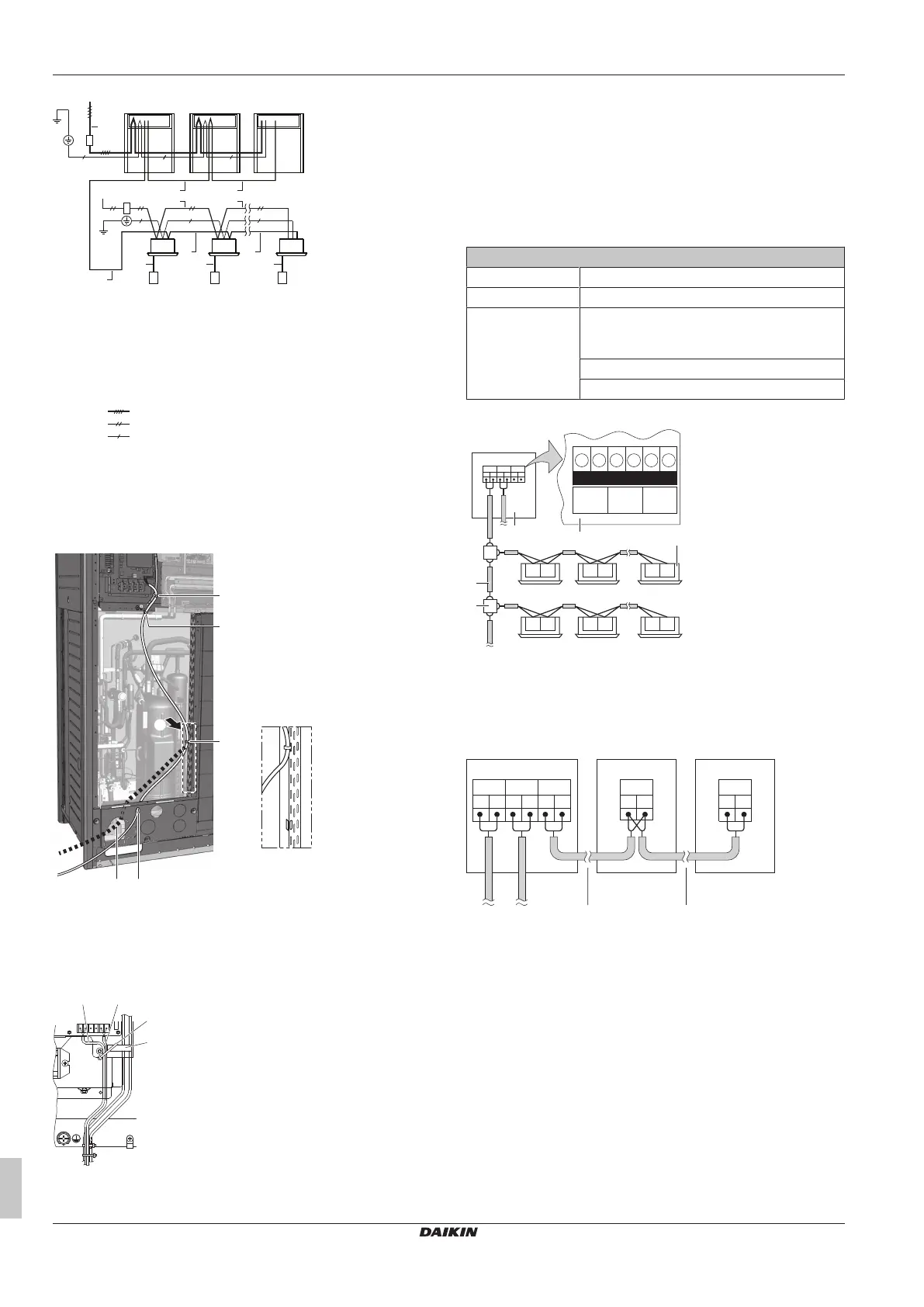
a Field power supply (with earth leakage protector)
b Main switch
c Earth connection
d Outdoor unit
e Indoor unit
f User interface
g Indoor power supply wiring (sheathed cable) (230V)
h Interconnection wiring (sheathed cable) (16V)
i Outdoor power supply wiring (sheathed cable)
Power supply 3N~50Hz
Power supply 1~50Hz
Earth wiring
15.4 To route and fix the
interconnection wiring
Interconnection wiring can be routed through the front side only. Fix
it to the upper mounting hole.
b a
c
d
c
A
A
a Interconnection wiring (possibility 1)
(a)
b Interconnection wiring (possibility 2)
(a)
c Tie wrap. Fix to factory-mounted low voltage wiring.
d Tie wrap.
(a)
Knockout hole has to be removed. Close the hole to
avoid small animals or dirt from entering.
c
d
a b
Fix to the indicated plastic brackets using field supplied clamping
material.
a Wiring between the units (indoor-outdoor) (F1/F2 left)
b Internal interconnection wiring (Q1/Q2)
c Plastic bracket
d Field supplied clamps
15.5 To connect the interconnection
wiring
The wiring from the indoor units must be connected to the F1/F2
(In‑Out) terminals on the PCB in the outdoor unit.
Indoor-outdoor connection requirements
Voltage 220~240V
Frequency 50Hz
Wire size Only use harmonised wiring providing double
insulation and suitable for the applicable
voltage
2 core cable
0.75 to1.25mm²
In case of single outdoor unit installation
F1 F2 F1 F2 Q1 Q2
F1 F1F2 F2 Q1 Q2
F1 F2 F1 F2 F1 F2
F1 F2 F1 F2 F1 F2
b
c
a
d
e
TO IN/D UNIT
TO OUT/D UNIT TO MULTI UNIT
A1P
a Outdoor unit PCB (A1P)
b Use the conductor of sheathed wire (2 wire) (no polarity)
c Terminal board (field supply)
d Indoor unit
e Outdoor unit
In case of multi outdoor unit installation
F1 F2 F1 F2 Q1 Q2 Q1 Q2
A1P
d de
f
ba c
Q1 Q2
a Unit A (master outdoor unit)
b Unit B (slave outdoor unit)
c Unit C (slave outdoor unit)
d Master/slave interconnection (Q1/Q2)
e Outdoor/indoor interconnection (F1/F2)
f Outdoor unit/other system interconnection (F1/F2)
▪ The interconnecting wiring between the outdoor units in the same
piping system must be connected to the Q1/Q2 (Out Multi)
terminals. Connecting the wires to the F1/F2 terminals results in
system malfunction.
▪ The wiring for the other systems must be connected to the F1/F2
(Out-Out) terminals of the PCB in the outdoor unit to which the
interconnecting wiring for the indoor units is connected.
▪ The base unit is the outdoor unit to which the interconnecting
wiring for the indoor units is connected.
Tightening torque for the interconnection wiring terminal screws:
Bekijk gratis de handleiding van Daikin RXYLQ28T7Y1B, stel vragen en lees de antwoorden op veelvoorkomende problemen, of gebruik onze assistent om sneller informatie in de handleiding te vinden of uitleg te krijgen over specifieke functies.
Productinformatie
| Merk | Daikin |
| Model | RXYLQ28T7Y1B |
| Categorie | Niet gecategoriseerd |
| Taal | Nederlands |
| Grootte | 6679 MB |


