Daikin RXYA18A7Y1B handleiding
Handleiding
Je bekijkt pagina 16 van 64
9 Relocation
Installation and operation manual
16
RYMA5+RXYA8~20A7Y1B
VRV 5 heat pump
4P739915-1C – 2024.10
▪ A continuous low "shah" sound is heard when the system is in
cooling operation or at a stop. When the drain pump (optional
accessories) is in operation, this noise is heard.
▪ A "pishi-pishi" squeaking sound is heard when the system stops
after heating operation. Expansion and contraction of plastic parts
caused by temperature change make this noise.
▪ A low "sah", "choro-choro" sound is heard while the indoor unit is
stopped. When another indoor unit is in operation, this noise is
heard. In order to prevent oil and refrigerant from remaining in the
system, a small amount of refrigerant is kept flowing.
8.2.10 Symptom: Noise of air conditioners
(Indoor unit, outdoor unit)
▪ A continuous low hissing sound is heard when the system is in
cooling or defrost operation. This is the sound of refrigerant gas
flowing through both indoor and outdoor units.
▪ A hissing sound which is heard at the start or immediately after
stopping operation or defrost operation. This is the noise of
refrigerant caused by flow stop or flow change.
8.2.11 Symptom: Noise of air conditioners
(Outdoor unit)
When the tone of operating noise changes. This noise is caused by
the change of frequency.
8.2.12 Symptom: Dust comes out of the unit
When the unit is used for the first time in a long time. This is
because dust has gotten into the unit.
8.2.13 Symptom: The units can give off odours
The unit can absorb the smell of rooms, furniture, cigarettes, etc.,
and then emit it again.
8.2.14 Symptom: The outdoor unit fan does not
spin
During operation, the speed of the fan is controlled in order to
optimise product operation.
8.2.15 Symptom: The display shows "88"
This is the case immediately after the main power supply switch is
turned on and means that the user interface is in normal condition.
This continues for 1minute.
8.2.16 Symptom: The compressor in the outdoor
unit does not stop after a short heating
operation
This is to prevent refrigerant from remaining in the compressor. The
unit will stop after 5 to 10 minutes.
8.2.17 Symptom: The inside of an outdoor unit is
warm even when the unit has stopped
This is because the crankcase heater is warming the compressor so
that the compressor can start smoothly.
8.2.18 Symptom: Hot air can be felt when the
indoor unit is stopped
Several different indoor units are being run on the same system.
When another unit is running, some refrigerant will still flow through
the unit.
9 Relocation
Contact your dealer to remove and reinstall the entire unit. Moving
units requires technical expertise.
10 Disposal
This unit uses hydrofluorocarbon. Contact your dealer when
discarding this unit. It is required by law to collect, transport and
discard the refrigerant in accordance with the "hydrofluorocarbon
collection and destruction" regulations.
NOTICE
Do NOT try to dismantle the system yourself: dismantling
of the system, treatment of the refrigerant, oil and other
parts MUST comply with applicable legislation. Units
MUST be treated at a specialised treatment facility for
reuse, recycling and recovery.
For the installer
11 About the box
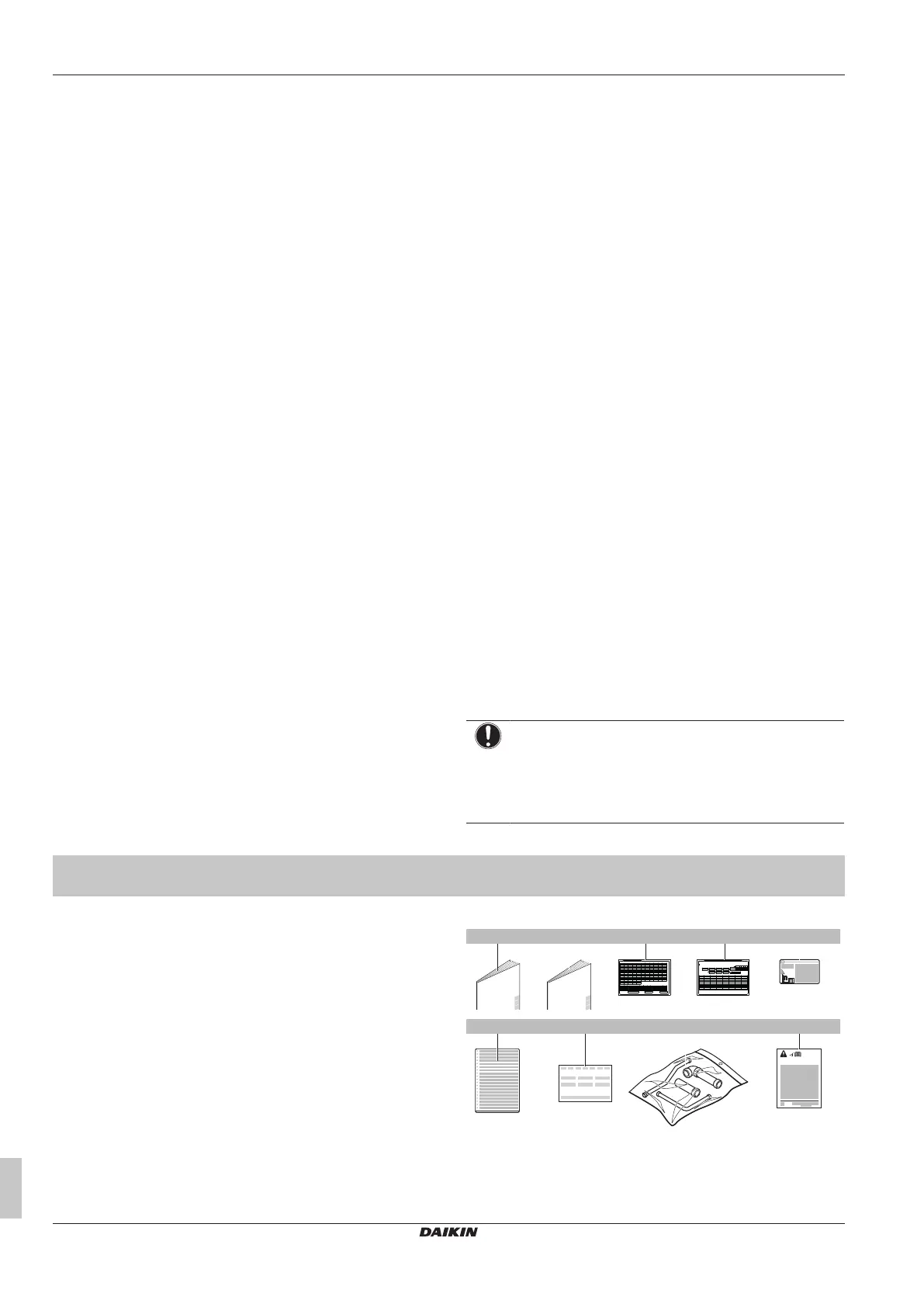
Keep the following in mind:
▪ At delivery, the unit MUST be checked for damage and
completeness. Any damage or missing parts MUST be reported
immediately to the claims agent of the carrier.
▪ Bring the packed unit as close as possible to its final installation
position to prevent damage during transport.
▪ Prepare in advance the path along which you want to bring the
unit to its final installation position.
11.1 To remove the accessories from
the outdoor unit
Make sure that all accessories are available in the unit.
a d
1× 1×
e
1×
3P328191-1
BE SURE TO FILL OUT THE BLANKS, WHICH ARE NEEDED FOR AFTER-SALE SERVICES.
REQUEST FOR THE INDICATION OF INSTALLATION INFORMATION
1. RECORD OF INDOOR UNIT MODEL AND INSTALLATION SITE
2. RECORD FOR SETTINGS (CONTENTS SEE INSTALLATION MANUAL)
SETTING
40
30
10
2019
9
29
3938
28
8
1817
7
27
3736
26
6
1615
5
25
3534
23 24
4321
INSTALLATION
MODELNAME
No.
12 13 14
504948474645
6059585756
64636261
11
2221
333231
44434241
5554535251
SITE
INSTALLATION
MODELNAME
No.
SITE
INSTALLATION
MODELNAME
No.
SITE
INSTALLATION
MODELNAME
No.
SITE
INSTALLATION
MODELNAME
No.
SITE
INSTALLATION
MODELNAME
No.
SITE
INSTALLATION
MODELNAME
No.
SITE
3. RECORD OF INSTALLATION DATE
6. AFTER EQUIPPING, PLEASE PUT IT ON THE BACK SIDE OF THE FRONT PLATE.
DAY MONTH YEAR
4. MODEL NAME 5. MANUFACTURING NUMBER
VALUE
REMARK DATE SETTING VALUE REMARK DATE
3P328192-1
3. FOR DETAILS CONCERNING PIPING SELECTION AND CALCULATION OR HOW TO OPERATE THE LEAK DETECTION FUNCTION, PLEASE REFER TO THE INSTALLATION MANUAL.
2. RECORD OF ADDITIONAL REFRIGERANT CHARGE AMOUNT AND RESULT OF LEAK CHECK OPERATION
REQUEST FOR THE INDICATION OF ADDITIONAL REFRIGERANT CHARGING AND LEAK DETECTION OPERATION RESULT
BE SURE TO FILL OUT THE BLANKS, WHICH ARE NEEDED FOR AFTER-SALE SERVICES.
1. CALCULATION OF ADDITIONAL REFRIGERANT CHARGING AMOUNT
4. AFTER FILLING IN THIS TABLE, PLEASE PUT IT ON THE SWITCH BOX COVER.
(m) x 0.18(m) x 0.37
kg
OUTDOOR
UNIT
(m) x 0.26
(m) x 0.12 (m) x 0.059
(m) x 0.022
ADDITIONAL CHARGING
AMOUNT
TOTAL LENGTH OF LIQUID
PIPE SIZE O22.2 x 0.37
TOTAL LENGTH OF LIQUID
PIPE SIZE O19.1 x 0.26
TOTAL LENGTH OF LIQUID
PIPE SIZE O15.9 x 0.18
TOTAL LENGTH OF LIQUID
PIPE SIZE O12.7 x 0.12
TOTAL LENGTH OF LIQUID
PIPE SIZE O9.5 x 0.059
TOTAL LENGTH OF LIQUID
PIPE SIZE O6.4 x 0.022
105%< CR < 130%
50%< CR < 105%
50%< CR < 70%
70%< CR < 85%
85%< CR < 105%
105%< CR < 130%
8HP
Total indoor unit
capacity connection
ratio (CR)
10-12HP
14-16HP
18-20HP
2.0
1.5
1.5
1.2
1.5
1
1
0.7
1.0
0.5
0.5
0.3
0.5
0
0
0
1.0
0.5
0.5
0.5
0.5
0
0
0
Total indoor unit capacity
when piping length <30m
Total indoor unit capacity
when piping length >30m
kg
1.3
1.1
0.9
RYYQ18-20
RYYQ14-16
RYYQ8~12
kg
ONLY FOR RYYQ8~20 MODELS
DATE
AMOUNT
CALCULATE THE ADDITIONAL REFRIGERANT CHARGING AMOUNT BASED ON THE FORMULA BELOW BEFORE CHARGING.
SHIPMENT (INDICATED ON THE MACHINE NAMEPLATE) AND THE ADDITIONAL AMOUNT SHOWN AS FOLLOWS :
WHEN RE-CHARGING TOTAL AMOUNT OF REFRIGERANT , CHARGE THE TOTAL OF THE AMOUNT CHARGED AT
RESULT LEAK CHECK
DATE
AMOUNT
RESULT LEAK CHECK
DATE
AMOUNT
RESULT LEAK CHECK
DATE
AMOUNT
RESULT LEAK CHECK
c
1×
b
1×
f g
1×
h
1×
i
1×1×
a General safety precautions
b Installation manual and operation manual
c Additional refrigerant charge label
d Installation information sticker
e Fluorinated greenhouse gases label
f Multilingual fluorinated greenhouse gases label
Bekijk gratis de handleiding van Daikin RXYA18A7Y1B, stel vragen en lees de antwoorden op veelvoorkomende problemen, of gebruik onze assistent om sneller informatie in de handleiding te vinden of uitleg te krijgen over specifieke functies.
Productinformatie
| Merk | Daikin |
| Model | RXYA18A7Y1B |
| Categorie | Niet gecategoriseerd |
| Taal | Nederlands |
| Grootte | 11397 MB |


