Daikin RXYA13A7Y1B handleiding
Handleiding
Je bekijkt pagina 43 van 64
18 Configuration
Installation and operation manual
43
RYMA5+RXYA8~20A7Y1B
VRV 5 heat pump
4P739915-1C – 2024.10
Multiple outdoor units
To connect the power supply for multiple outdoor units to each other,
ring tongues have to be used. No bare cable can be used.
In that case, the ring washer that is installed by default should be
removed.
Attach both cables to the power supply terminal as indicated below:
L1 L2 L3 N
17.9 To connect the external outputs
SVS and SVEO output
The SVS and SVEO outputs are contacts on terminal X2M.
The SVS output is a contact on terminal X2M that closes in case a
leak is detected, failure or disconnection of the R32 sensor (located
in the SV unit or indoor unit).
The SVEO output is a contact on terminal X2M that closes in case of
occurrence of general errors. See "8.1Error codes: Overview"[414]
and "22.1.1 Error codes: Overview"[452] for errors that will trigger
this output.
Outdoor output connection requirements
Voltage 220~240V
Maximum current 0.5A
Wire size Only use harmonised wiring providing double
insulation and suitable for the applicable
voltage.
2-core cable
Minimum cable section of 0.75mm²
NOTICE
Do NOT use the outputs as a power source. Instead, use
each output to energize a relay that controls the external
circuit.
WHT
SVEO SVS
BLK GRY PPL
ba
c
X2M
a SVEO output terminals (1 and 2)
b SVS output terminals (1 and 2)
c Cable to SVS output device (example)
Example:
X2M
(SVS)
a
1
2
c
b d
a SVS output terminal
b Relay
c AC power supply 220~240VAC
d External alarm
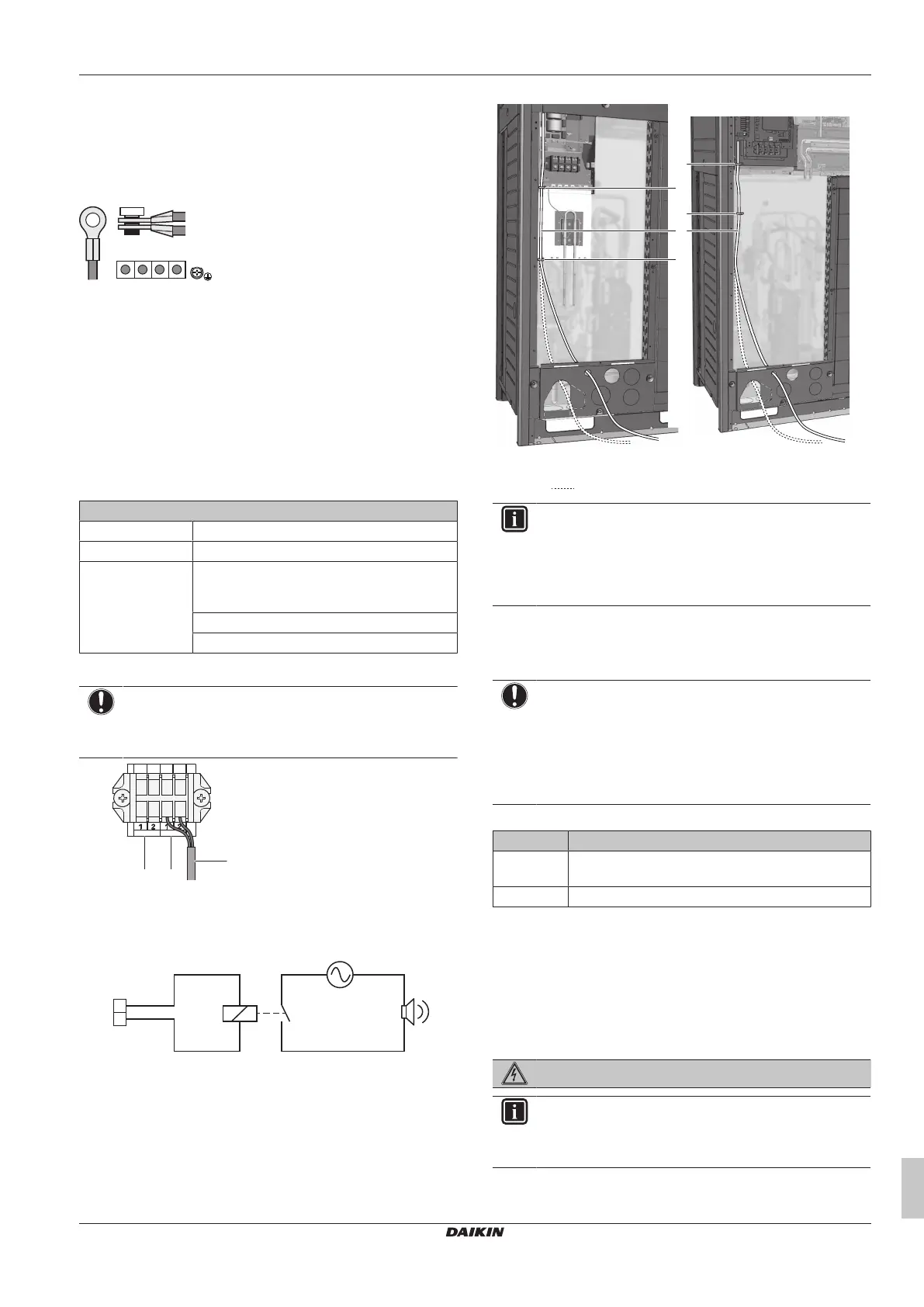
Cable routing
Route the SVEO or SVS output cable as indicated below.
5~12 HP 14~20 HP
a
b
b
b
b
a Output cable (SVEO or SVS)(field supply)
b Cable tie (accessory)
Alternate routing
INFORMATION
Sound data about the refrigerant leakage alarm are
available in the technical data sheet of the user interface.
E.g. the BRC1H52* controller generates an alarm of 65dB
(sound pressure, measured at 1 m distance from the
alarm).
17.10 To check the insulation resistance
of the compressor
NOTICE
If, after installation, refrigerant accumulates in the
compressor, the insulation resistance over the poles can
drop, but if it is at least 1MΩ, then the unit will not break
down.
▪ Use a 500V mega-tester when measuring insulation.
▪ Do NOT use a mega-tester for low voltage circuits.
1 Measure the insulation resistance over the poles.
If Then
≥1MΩ Insulation resistance is OK. This procedure is
finished.
<1MΩ Insulation resistance is not OK. Go to the next step.
2 Turn ON the power and leave it on for 6hours.
Result: The compressor will heat up and evaporate any
refrigerant in the compressor.
3 Measure the insulation resistance again.
18 Configuration
DANGER: RISK OF ELECTROCUTION
INFORMATION
It is important that all information in this chapter is read
sequentially by the installer and that the system is
configured as applicable.
Bekijk gratis de handleiding van Daikin RXYA13A7Y1B, stel vragen en lees de antwoorden op veelvoorkomende problemen, of gebruik onze assistent om sneller informatie in de handleiding te vinden of uitleg te krijgen over specifieke functies.
Productinformatie
| Merk | Daikin |
| Model | RXYA13A7Y1B |
| Categorie | Niet gecategoriseerd |
| Taal | Nederlands |
| Grootte | 11397 MB |


