Daikin RXF60D5V1B handleiding
Handleiding
Je bekijkt pagina 13 van 140
12 Technical data
Installation manual
13
RXF50~71D5V1B
R32 split series
3P645642-2E – 2021.10
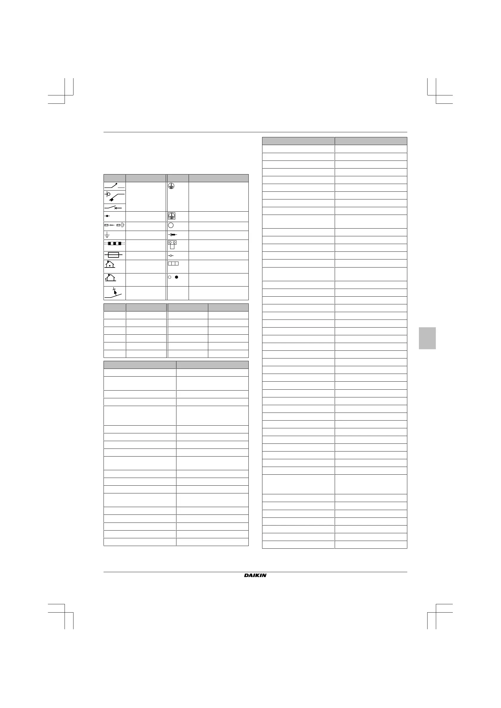
12.1.1 Unified wiring diagram legend
For applied parts and numbering, refer to the wiring diagram on the
unit. Part numbering is by Arabic numbers in ascending order for
each part and is represented in the overview below by "*" in the part
code.
Symbol
Meaning Symbol Meaning
Circuit breaker Protective earth
Connection Protective earth (screw)
,
Connector
A
Rectifier
Earth Relay connector
Field wiring Short-circuit connector
Fuse Terminal
INDOOR
Indoor unit Terminal strip
OUTDOOR
Outdoor unit Wire clamp
Residual current
device
Symbol
Colour Symbol Colour
BLK
Black ORG Orange
BLU
Blue PNK Pink
BRN
Brown PRP, PPL Purple
GRN
Green RED Red
GRY
Grey WHT White
YLW
Yellow
Symbol
Meaning
A*P
Printed circuit board
BS*
Pushbutton ON/OFF, operation
switch
BZ, H*O
Buzzer
C*
Capacitor
AC*, CN*, E*, HA*, HE*, HL*,
HN*, HR*, MR*_A, MR*_B, S*, U,
V, W, X*A, K*R_*, NE
Connection, connector
D*, V*D
Diode
DB*
Diode bridge
DS*
DIP switch
E*H
Heater
FU*, F*U, (for characteristics,
refer to PCB inside your unit)
Fuse
FG*
Connector (frame ground)
H*
Harness
H*P, LED*, V*L
Pilot lamp, light emitting diode
HAP
Light emitting diode (service
monitor green)
HIGH VOLTAGE
High voltage
IES
Intelligent eye sensor
IPM*
Intelligent power module
K*R, KCR, KFR, KHuR, K*M
Magnetic relay
L
Live
Symbol
Meaning
L*
Coil
L*R
Reactor
M*
Stepper motor
M*C
Compressor motor
M*F
Fan motor
M*P
Drain pump motor
M*S
Swing motor
MR*, MRCW*, MRM*, MRN*
Magnetic relay
N
Neutral
n=*, N=*
Number of passes through ferrite
core
PAM
Pulse-amplitude modulation
PCB*
Printed circuit board
PM*
Power module
PS
Switching power supply
PTC*
PTC thermistor
Q*
Insulated gate bipolar transistor
(IGBT)
Q*C
Circuit breaker
Q*DI, KLM
Earth leak circuit breaker
Q*L
Overload protector
Q*M
Thermo switch
Q*R
Residual current device
R*
Resistor
R*T
Thermistor
RC
Receiver
S*C
Limit switch
S*L
Float switch
S*NG
Refrigerant leak detector
S*NPH
Pressure sensor (high)
S*NPL
Pressure sensor (low)
S*PH, HPS*
Pressure switch (high)
S*PL
Pressure switch (low)
S*T
Thermostat
S*RH
Humidity sensor
S*W, SW*
Operation switch
SA*, F1S
Surge arrester
SR*, WLU
Signal receiver
SS*
Selector switch
SHEET METAL
Terminal strip fixed plate
T*R
Transformer
TC, TRC
Transmitter
V*, R*V
Varistor
V*R
Diode bridge, Insulated-gate
bipolar transistor (IGBT) power
module
WRC
Wireless remote controller
X*
Terminal
X*M
Terminal strip (block)
Y*E
Electronic expansion valve coil
Y*R, Y*S
Reversing solenoid valve coil
Z*C
Ferrite core
ZF, Z*F
Noise filter
Bekijk gratis de handleiding van Daikin RXF60D5V1B, stel vragen en lees de antwoorden op veelvoorkomende problemen, of gebruik onze assistent om sneller informatie in de handleiding te vinden of uitleg te krijgen over specifieke functies.
Productinformatie
| Merk | Daikin |
| Model | RXF60D5V1B |
| Categorie | Niet gecategoriseerd |
| Taal | Nederlands |
| Grootte | 23881 MB |


