Daikin REYA14A7Y1B handleiding
Handleiding
Je bekijkt pagina 16 van 60
11 About the box
Installation and operation manual
16
REMA5+REYA8~20A7Y1B
VRV 5 heat recovery
4P684060-1C – 2024.10
For the installer
11 About the box
Keep the following in mind:
▪ At delivery, the unit MUST be checked for damage and
completeness. Any damage or missing parts MUST be reported
immediately to the claims agent of the carrier.
▪ Bring the packed unit as close as possible to its final installation
position to prevent damage during transport.
▪ Prepare in advance the path along which you want to bring the
unit to its final installation position.
11.1 To remove the accessories from
the outdoor unit
Make sure that all accessories are available in the unit.
a d
1× 1×
e
1×
3P328191-1
BE SURE TO FILL OUT THE BLANKS, WHICH ARE NEEDED FOR AFTER-SALE SERVICES.
REQUEST FOR THE INDICATION OF INSTALLATION INFORMATION
1. RECORD OF INDOOR UNIT MODEL AND INSTALLATION SITE
2. RECORD FOR SETTINGS (CONTENTS SEE INSTALLATION MANUAL)
SETTING
40
30
10
2019
9
29
3938
28
8
1817
7
27
3736
26
6
1615
5
25
3534
23 24
4321
INSTALLATION
MODELNAME
No.
12 13 14
504948474645
6059585756
64636261
11
2221
333231
44434241
5554535251
SITE
INSTALLATION
MODELNAME
No.
SITE
INSTALLATION
MODELNAME
No.
SITE
INSTALLATION
MODELNAME
No.
SITE
INSTALLATION
MODELNAME
No.
SITE
INSTALLATION
MODELNAME
No.
SITE
INSTALLATION
MODELNAME
No.
SITE
3. RECORD OF INSTALLATION DATE
6. AFTER EQUIPPING, PLEASE PUT IT ON THE BACK SIDE OF THE FRONT PLATE.
DAY MONTH YEAR
4. MODEL NAME 5. MANUFACTURING NUMBER
VALUE
REMARK DATE SETTING VALUE REMARK DATE
3P328192-1
3. FOR DETAILS CONCERNING PIPING SELECTION AND CALCULATION OR HOW TO OPERATE THE LEAK DETECTION FUNCTION, PLEASE REFER TO THE INSTALLATION MANUAL.
2. RECORD OF ADDITIONAL REFRIGERANT CHARGE AMOUNT AND RESULT OF LEAK CHECK OPERATION
REQUEST FOR THE INDICATION OF ADDITIONAL REFRIGERANT CHARGING AND LEAK DETECTION OPERATION RESULT
BE SURE TO FILL OUT THE BLANKS, WHICH ARE NEEDED FOR AFTER-SALE SERVICES.
1. CALCULATION OF ADDITIONAL REFRIGERANT CHARGING AMOUNT
4. AFTER FILLING IN THIS TABLE, PLEASE PUT IT ON THE SWITCH BOX COVER.
(m) x 0.18(m) x 0.37
kg
OUTDOOR
UNIT
(m) x 0.26
(m) x 0.12 (m) x 0.059
(m) x 0.022
ADDITIONAL CHARGING
AMOUNT
TOTAL LENGTH OF LIQUID
PIPE SIZE O22.2 x 0.37
TOTAL LENGTH OF LIQUID
PIPE SIZE O19.1 x 0.26
TOTAL LENGTH OF LIQUID
PIPE SIZE O15.9 x 0.18
TOTAL LENGTH OF LIQUID
PIPE SIZE O12.7 x 0.12
TOTAL LENGTH OF LIQUID
PIPE SIZE O9.5 x 0.059
TOTAL LENGTH OF LIQUID
PIPE SIZE O6.4 x 0.022
105%< CR < 130%
50%< CR < 105%
50%< CR < 70%
70%< CR < 85%
85%< CR < 105%
105%< CR < 130%
8HP
Total indoor unit
capacity connection
ratio (CR)
10-12HP
14-16HP
18-20HP
2.0
1.5
1.5
1.2
1.5
1
1
0.7
1.0
0.5
0.5
0.3
0.5
0
0
0
1.0
0.5
0.5
0.5
0.5
0
0
0
Total indoor unit capacity
when piping length <30m
Total indoor unit capacity
when piping length >30m
kg
1.3
1.1
0.9
RYYQ18-20
RYYQ14-16
RYYQ8~12
kg
ONLY FOR RYYQ8~20 MODELS
DATE
AMOUNT
CALCULATE THE ADDITIONAL REFRIGERANT CHARGING AMOUNT BASED ON THE FORMULA BELOW BEFORE CHARGING.
SHIPMENT (INDICATED ON THE MACHINE NAMEPLATE) AND THE ADDITIONAL AMOUNT SHOWN AS FOLLOWS :
WHEN RE-CHARGING TOTAL AMOUNT OF REFRIGERANT , CHARGE THE TOTAL OF THE AMOUNT CHARGED AT
RESULT LEAK CHECK
DATE
AMOUNT
RESULT LEAK CHECK
DATE
AMOUNT
RESULT LEAK CHECK
DATE
AMOUNT
RESULT LEAK CHECK
c
1×
b
1×
f g
1×
h
1×
i
1×1×
a General safety precautions
b Installation manual and operation manual
c Additional refrigerant charge label
d Installation information sticker
e Fluorinated greenhouse gases label
f Multilingual fluorinated greenhouse gases label
g Declaration of conformity
h Piping accessory bag
i Transportation stay removal label (only for 5~12HP)
11.2 Accessory pipes: Diameters
Accessory pipes HP Øa [mm] Øb [mm]
Gas pipe
▪ Front connection
ID Øa
ID Øb
▪ Bottom connection
ID Øa
OD Øb
5 25.4 19.1
8
10
12 22.2
14
16
18
20 28.6
Liquid pipe
▪ Front connection
ID Øb
ID Øa
▪ Bottom connection
ID Øb
ID Øa
5 9.5 9.5
8
10
12 12.7
14 12.7
16
18
20
Accessory pipes HP Øa [mm] Øb [mm]
High pressure/low pressure gas
pipe
▪ Front connection
ID Øa
ID Øb
▪ Bottom connection
ID Øa
OD Øb
5 19.1 15.9
8
10
12 19.1
14
16
18
20 22.2
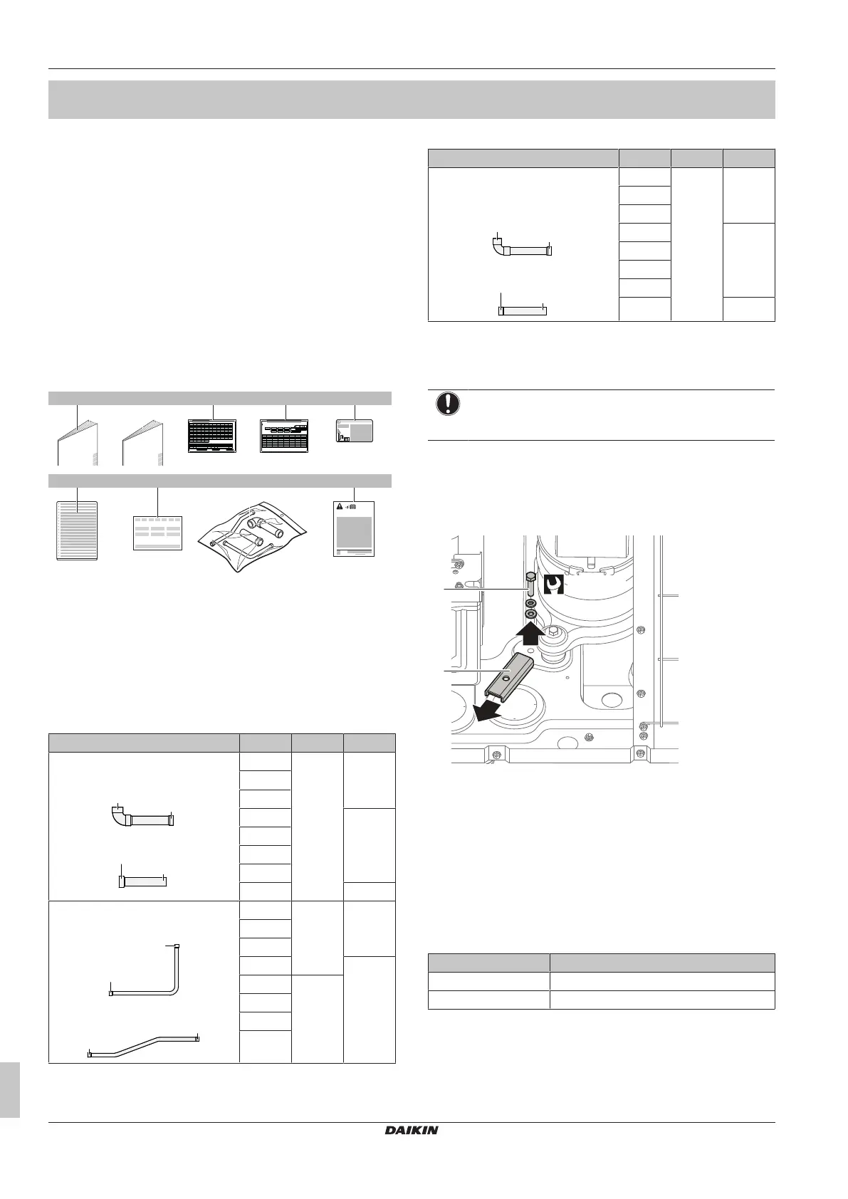
11.3 To remove the transportation stay
(only for 5~12 HP)
NOTICE
If the unit is operated with the transportation stay attached,
abnormal vibration or noise may be generated.
The transportation stay for protecting the unit during transport must
be removed. Proceed as shown in the figure and procedure below.
1 Remove the bolt (a) and washers.
2 Remove the transportation stay (b) as shown in the figure
below.
1
2
(12.3 N·m)
a
b
a Bolt
b Transportation stay
12 About the units and options
12.1 About the outdoor unit
This installation manual concerns the VRV 5, full inverter driven,
heat recovery system.
Model line up:
Model Description
REYA8~20 Heat recovery model for single or multi-use
REMA5 Heat recovery model for multi-use only
Depending on the type of outdoor unit which is chosen, some
functionality will or will not exist. It will be indicated throughout this
installation manual and brought to your attention. Certain features
have exclusive model rights.
These units are intended for outdoor installation and aimed for heat
pump applications including air to air applications.
Bekijk gratis de handleiding van Daikin REYA14A7Y1B, stel vragen en lees de antwoorden op veelvoorkomende problemen, of gebruik onze assistent om sneller informatie in de handleiding te vinden of uitleg te krijgen over specifieke functies.
Productinformatie
| Merk | Daikin |
| Model | REYA14A7Y1B |
| Categorie | Niet gecategoriseerd |
| Taal | Nederlands |
| Grootte | 10147 MB |


