Daikin REMA5A7Y1B9 handleiding
Handleiding
Je bekijkt pagina 21 van 64
13 Special requirements for R32 units
Installation and operation manual
21
REMA5A7Y1B9+REYA8~20A7Y1B9
VRV 5 heat recovery
4P797563-1 – 2024.11
▪ Each of the rooms served by a ducted indoor unit installed in a
different room
The room area can be determined by projecting the walls, doors and
partitions to the floor and calculate the enclosed area. Spaces
connected by only false ceilings, ductwork, or similar connections
are NOT considered a single space.
The area of the smallest room calculated above is used in the next
step to determine the maximum allowable indoor capacity that can
be connected to that port.
Step2 – Use the table below to determine the maximum total indoor
unit capacity (sum of all connected indoor units) that is allowed for a
single BS unit branch pipe port. In case a ducted indoor unit is
serving a different room than where it is installed, the restrictions of
the room area apply to both the indoor installation room and the
conditioned room separately. Supply and return air shall be directly
ducted to that room.
Area of installed/
conditioned room [m²]
Maximum total indoor unit capacity class
1 indoor unit per
branch pipe port
(a)
2~5 indoor units per branch pipe port
40m after 1
st
branch
(b)
90m after 1
st
branch
(c)
<5 — — —
5 10 — —
6 25 — —
7 32 — —
8 40 — —
9 71 — —
10 80 — —
11 80 20 —
12 80 25 —
13 80 32 —
14 80 32 —
15 125 40 —
20 200 50 40
25 250 71 71
30 250 125 125
35 250 200 200
40 250 200 200
≥45 250 250 250
(a)
One indoor unit connected to a single branch pipe port.
(b)
Two to five indoor units connected to a single branch pipe port,
40m after first refrigerant branch.
(c)
Two to five indoor units connected to a single branch pipe port,
90m after first refrigerant branch (size-up of liquid pipe, see
"15.1Preparing refrigerant piping"[428]).
Notes:
▪ The values in the table are under the assumption of worst case
indoor unit volume and 40m piping between indoor and BS unit
and an installation height up to 2.2 m (bottom of indoor unit or
bottom of duct openings). In VRV Xpress it is possible to add
custom piping lengths, installation heights above 2.2 m and
custom indoor units which can lead to lower minimum room area
requirements.
▪ In case the capacity class allowed per branch pipe port is bigger
than 140, combine two ports. For more information and installation
of the BS unit, please refer to the installation and operation
manual delivered with the BS unit.
▪ In case multiple indoor units are connected to the same branch
pipe port, the sum of the connected indoor unit capacity classes
needs to be equal or less than the value indicated in the table.
▪ In case indoor units connected to the same branch pipe port are
split over different rooms, the area of the smallest room needs to
be considered.
▪ Round down the derived values.
▪ If shut-off valves are not sufficient as safety measure due to a
smaller installation area, natural ventilation can be used as safety
measure.
Step3 – The total indoor capacity connected to a branch pipe port
(or pair of branch pipe ports in case of FXMA200/250) MUST be
equal or less than the capacity limit that is derived from the table.
If NOT, change the installation and repeat all of the above steps.
Possible changes:
▪ Increase the area of smallest room (installed & conditioned)
connected to the same branch pipe port.
▪ Reduce the indoor capacity connected to the same branch pipe
port to equal or below the limit.
▪ Split indoor capacity over two separate branch pipe ports.
▪ Fine tune system with more detailed calculations in VRV Xpress.
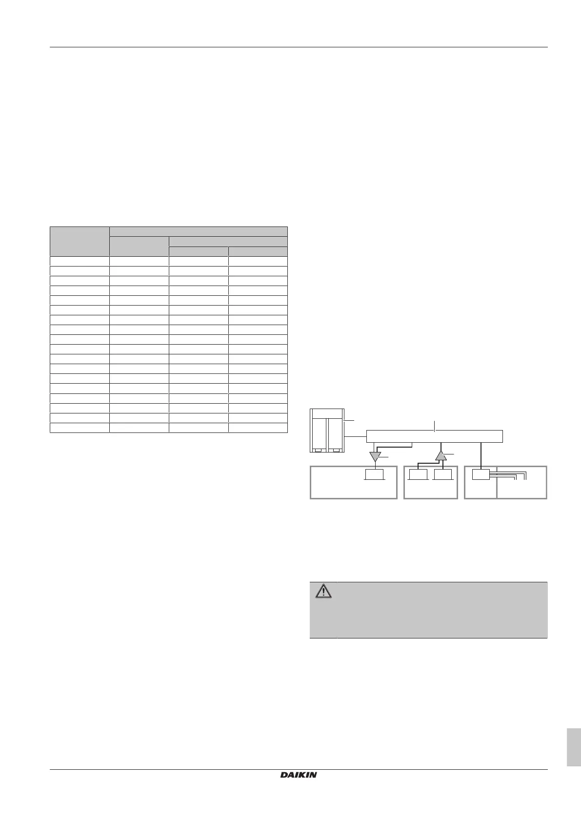
Example
VRV system serving three rooms via one BS unit. Room1 (20m²) is
served by one indoor unit (32 class) connected to port A. Room2
(42 m²) is served by two indoor units (2×50 class) connected to
portB (no extension and liquid pipe size up has been done). Room3
(150 m²) is served by one indoor unit (200 class) connected to
portsC and D.
Port A is connected to an indoor unit installed in room 1a, that is
serving a different room (room 1b) than where it is installed. The
smallest room size needs to be considered: 20 m². Use the table
under Step2 to find the maximum capacity class limit of the indoor
unit: 140. The selected indoor unit is 32 →OK.
Port B only serves room 2: use the table under Step 2 to find the
maximum capacity class limit of the sum of the indoor units. 42m² is
rounded down to 40m²: 200. The sum of both indoor units is exactly
100 →OK.
PortsC and D are combined and must be considered as one branch
pipe. They only serve room3: Use the table under Step2 to find the
maximum capacity class limit of the indoor unit: 250. The selected
indoor unit is 200 →OK.
50 50200
b
a
Room 1a
20
m²
Room 1b
40
m²
Room 3
150
m²
Room 2
42
m²
D C B A
32
c
c
A~D Branch pipe port A~D
a Outdoor unit
b BS unit
c Indoor branch kit (refnet)
Room Room
32/50/200 Indoor unit capacity
13.4.2 Alarm
WARNING
Do NOT use 'Alarm' as the ONLY safety measure in case
the indoor unit is installed in an occupied space where
people are restricted in their movement. Combine or use
another safety measure.
R32 safety system compatible remote controllers (e.g. BRC1H52/82*
or later type) used with the indoor units have a built-in alarm as a
safety measure. For installation of the remote controller, please refer
to the installation and operation manual delivered with the remote
controller.
Each indoor unit must be connected with a R32 safety system
compatible remote controller (e.g. BRC1H52/82* or later type).
These remote controllers have implemented safety measures that
will warn the user visually and audibly in case of a leak.
For installation of the remote controller, it is mandatory to follow the
requirements.
Bekijk gratis de handleiding van Daikin REMA5A7Y1B9, stel vragen en lees de antwoorden op veelvoorkomende problemen, of gebruik onze assistent om sneller informatie in de handleiding te vinden of uitleg te krijgen over specifieke functies.
Productinformatie
| Merk | Daikin |
| Model | REMA5A7Y1B9 |
| Categorie | Niet gecategoriseerd |
| Taal | Nederlands |
| Grootte | 10896 MB |


