Daikin REMA5A7Y1B9 handleiding
Handleiding
Je bekijkt pagina 19 van 64
13 Special requirements for R32 units
Installation and operation manual
19
REMA5A7Y1B9+REYA8~20A7Y1B9
VRV 5 heat recovery
4P797563-1 – 2024.11
Step2 – Determine the smallest area out of:
▪ The room where an indoor unit is installed
▪ Each of the rooms served by a ducted indoor unit installed in a
different room
The room area can be determined by projecting the walls, doors and
partitions to the floor and calculating the enclosed area. Spaces
connected by only false ceilings, ductwork, or similar connections
are not considered a single space.
Step 3 – Use the graphs or tables (see "Figure 1" [4 2] at the
beginning of this manual) to determine the required safety measures
for the indoor unit.
m Total refrigerant charge in the system [kg]
A
min
Minimum room area [m²]
(a) Lowest underground floor (=Lowest underground floor)
(b) All other floors (=All other floors)
(c) No safety measure (=No safety measure)
(d) Alarm + shut-off valve OR Natural ventilation (=Alarm +
shut-off valve OR Natural ventilation)
(e) NOT allowed (=NOT allowed)
(f) Alarm + shut-off valve [BS unit] OR Alarm + natural
ventilation + shut-off valve [BS unit] (=Alarm + shut-off
valve [BS unit] OR Alarm + natural ventilation + shut-off
valve [BS unit])
Use the total amount of refrigerant in the system and the smallest
area of the room in which the indoor unit is installed/conditioning to
check which safety measure is required.
Note: When "No safety measure" is required, it is still allowed to
apply natural ventilation or alarm or shut-off valve (BS unit) if
wanted. Follow the respective instructions as described further
below.
Note: When natural ventilation is required, it is still allowed to apply
alarm or shut-off valve (BS unit) if wanted. Follow the respective
instructions as described further below.
Use the first graph (Lowest underground floor
(a)
) in case the indoor
unit is installed/conditioning in the lowest underground floor of a
building. For other floors, use the second graph (All other floors
(b)
).
OTHER FLOORS
LOWEST UNDERGROUND FLOOR
The graphs and table are based on an installation height of the
indoor unit up to 2.2 m (bottom of the indoor unit or bottom of the
duct openings). See "14.1.1 Installation site requirements of the
outdoor unit"[426].
If the installation height is more than 2.2m, different boundaries for
the applicable safety measures can apply. To know which safety
measure is required in case the installation height is more than
2.2m, refer to the online tool (VRV Xpress).
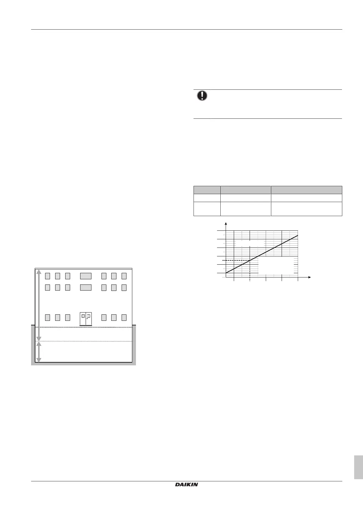
NOTICE
Indoor units and the bottom of duct openings cannot be
installed lower than 1.8m from the lowest point of the floor,
except for floor standing indoor units (e.g. FXNA)
Example
The total amount of refrigerant in the VRV system is 20kg. All indoor
units are installed in spaces that do NOT belong to the lowest
underground floor of the building. The space in which the first indoor
unit is installed has a room area of 50 m², the space in which the
second indoor unit is installed has a room area of 15m².
▪ Based on the graph for "All other floors" (All other floors), the room
area limit is 40m² for No safety measure" (No safety measures).
▪ This means that the following safety measures are required:
BS unit Room area Required safety measure
1 A=50m²≥40m² No safety measures
2 A=15m²<40m² Alarm + natural ventilation OR
Alarm + shut-off valve (BS unit)
0
10
20
30
40
50
70
90
110
80
60
100
5
10 20 30 40 50
2515 35 45
m [kg]
A
min
[m
2
]
No safety measure
(c)
Alarm + shut-off valve [BS unit]
OR
Alarm + natural ventilation
+ shut-off valve [BS unit]
(f)
m Total refrigerant charge in the system [kg]
A
min
Minimum room area [m²]
(a) Lowest underground floor (=Lowest underground floor)
(b) All other floors (=All other floors)
(c) No safety measure (=No safety measure)
(d) Alarm + shut-off valve OR Natural ventilation (=Alarm +
shut-off valve OR Natural ventilation)
(e) NOT allowed (=NOT allowed)
(f) Alarm + shut-off valve [BS unit] OR Alarm + natural
ventilation + shut-off valve [BS unit] (=Alarm + shut-off
valve [BS unit] OR Alarm + natural ventilation + shut-off
valve [BS unit])
Bekijk gratis de handleiding van Daikin REMA5A7Y1B9, stel vragen en lees de antwoorden op veelvoorkomende problemen, of gebruik onze assistent om sneller informatie in de handleiding te vinden of uitleg te krijgen over specifieke functies.
Productinformatie
| Merk | Daikin |
| Model | REMA5A7Y1B9 |
| Categorie | Niet gecategoriseerd |
| Taal | Nederlands |
| Grootte | 10896 MB |


