Handleiding
Je bekijkt pagina 14 van 24
12 Unit installation
Installation and operation manual
14
FXSN-B
CO₂ VRV system air conditioner
3P672850-3C – 2024.11
A In case of rear suction installation 231mm
In case of installation with canvas duct (field supply)
350~530mm
a Metal clamp (accessory)
b Drain hose (accessory)
c Rising drain piping (vinyl pipe of 25mm nominal diameter
and 32mm outer diameter) (field supply)
d Hanging bars (field supply)
▪ Combining drain pipes. You can combine drain pipes. Make
sure to use drain pipes and T-joints with the correct gauge for the
operating capacity of the units.
≥100≤625
(mm)
a
a T-joint
To connect the drain piping to the indoor unit
NOTICE
Incorrect connection of the drain hose might cause leaks,
and damage the installation space and surroundings.
a Drain outlet for maintenance
b Refrigerant pipes
c Drain pipe connection
1 Push the drain hose as far as possible over the drain pipe
connection.
2 Tighten the metal clamp until the screw head is less than 4mm
from the metal clamp part.
3 Check for water leaks (see "To check for water leaks"[414]).
4 Wind the large sealing pad (= insulation) around the metal
clamp and drain hose, and fix it with tie wraps (accessory).
5 Connect the drain piping to the drain hose.
ba
≤4 mm
A-A'
b
a
d
c
3
1
2~61
4
d
A'
e
5
2
c
AA
A'
a Drain pipe connection (attached to the unit)
b Drain hose (accessory)
c Metal clamp (accessory)
d Large sealing pad (accessory)
e Drain piping (field supply)
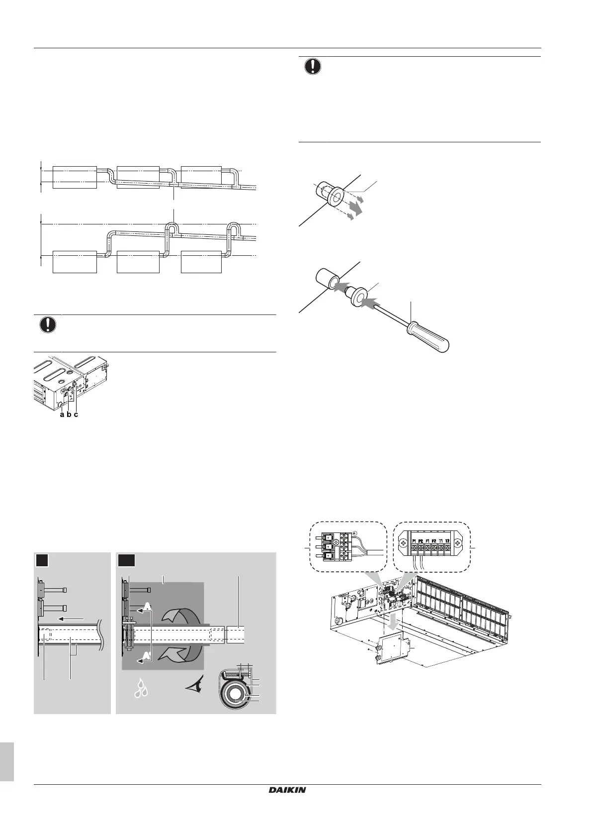
NOTICE
▪ Do NOT remove the drain pipe plug. Water might leak
out.
▪ Use the drain outlet only to discharge the water before
maintenance.
▪ Insert and remove the drain plug gently. Excessive
force may deform the drain socket of the drain pan.
Pull out the plug.
▪ Do NOT wiggle the plug up and down.
a
Push in the plug.
▪ Set the plug and push it in using a Phillips screwdriver.
a
b
a Drain plug
b Phillips screwdriver
To check for water leaks
The procedure differs depending on whether installation of the
system is already completed. When installation of the system is not
yet completed, temporarily connect the user interface and power
supply to the unit.
When installation of the system is not yet completed
1 Temporarily connect electrical wiring.
▪ Remove the service cover.
▪ Connect the power supply.
▪ Connect the user interface.
▪ Reattach the service cover.
L
N
a
b
c
a Power supply terminal block
b User interface terminal block
c Service cover with wiring diagram
2 Turn ON the power supply.
3 Start fan only operation (see the reference guide or the service
manual of the user interface).
4 Remove the water inlet cover (1 screw).
5 Gradually pour approximately 1 l of water through the water
inlet, and check for leaks.
Bekijk gratis de handleiding van Daikin FXSN80B2VEB, stel vragen en lees de antwoorden op veelvoorkomende problemen, of gebruik onze assistent om sneller informatie in de handleiding te vinden of uitleg te krijgen over specifieke functies.
Productinformatie
| Merk | Daikin |
| Model | FXSN80B2VEB |
| Categorie | Airco |
| Taal | Nederlands |
| Grootte | 3884 MB |


