Daikin FXFQ50AVEB handleiding
Handleiding
Je bekijkt pagina 9 van 16
Installation and operation manual
6
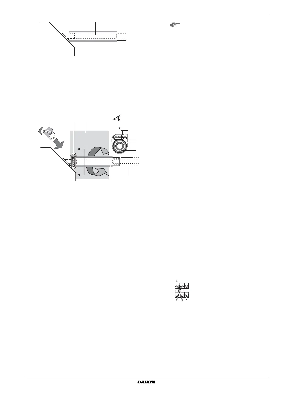
- Tighten the metal clamp until the screw head is less than
4 mm from the metal clamp part as indicated in the
illustration.
- After the testing of drain piping is finished, attach the drain
sealing pad (4) supplied with the unit over the uncovered
part of the drain socket (= between drain hose and unit
body).
- Wrap the supplied large sealing pad over the metal clamp
and drain hose to insulate and fix it with clamps.
- Insulate the complete drain piping inside the building (field
supply).
- If the drain hose cannot be sufficiently set on a slope, fit
the hose with drain raising piping (field supply).
How to perform piping (See figure 7)
1
Connect the drain hose to the drain raising pipes, and
insulate them.
2
Connect the drain hose to the drain outlet on the indoor unit,
and tighten it with the clamp.
Precautions
- Install the drain raising pipes at a height of less than
675 mm.
- Install the drain raising pipes at a right angle to the indoor
unit and no more than 300 mm from the unit.
- To prevent air bubbles, install the drain hose level or
slightly tilted up (≤75 mm).
Testing of drain piping
After piping work is finished, check if drainage flows smoothly.
Add approximately 1 l of water gradually through the air
discharge outlet.
Method of adding water. See figure 11.
C
heck the drainage flow.
In case electric wiring work is finished
Check drainage flow during COOL running, explained in "Test operation"
on page 9.
In case electric wiring work is not finished
- Remove the control box lid. Connect the power supply firmly to
the terminal. See figure 10.
- Reattach the control box lid and turn on the power.
- Do not touch the drain pump. It may result in electric shock.
- Confirm the drain operation looking at the drain socket.
- After checking the drainage flow, turn off the power, remove the
control box lid and disconnect the power supply from the
terminal again.
- Reattach the control box lid.
1 Drain socket (attached to the unit)
2 Drain hose (supplied with the unit)
1 Drain socket (attached to the unit)
2 Drain hose (supplied with the unit)
3 Metal clamp (supplied with the unit)
4 Drain sealing pad (supplied with the unit)
5 Large sealing pad (supplied with the unit)
6 Drain piping (field supply)
1 Ceiling slab
2 Hanger bracket
3 Adjustable range
4 Drain raising pipe (nominal diameter of vinyl pipe = 25 mm)
5 Drain hose (supplied with the unit)
6 Clamp metal (supplied with the unit)
21
1
6
2
4 3 5
4 mm
3
5
2
A
A'
A-A'
1
NOTE
The incline of attached drain hose should be
75 mm or less so that the drain socket does
not have to withstand additional force.
To ensure a downward slope of 1:100, install
hanging bars every 1 to 1.5 m.
When unifying multiple drain pipes, install the
pipes as shown in figure 9. Select converging
drain pipes whose gauge is suitable for the
operating capacity of the unit.
1 T-joint converging drain pipes
1 Plastic watering can (tube should be about 100 mm long)
2 Service drain outlet (with rubber plug) (Use this outlet to
drain water from the drain pan)
3 Drain pump location
4 Drain pipe
5 Drain socket (water flow view point)
1 Control box lid
2 Power supply wiring
3 Power supply terminal block
4 Clamp (field supply)
5 Unit transmission wiring
6 Terminal block for transmission wiring
7 Opening for cables
8 Wiring diagram label
(on the back side of the control box lid)
9 Earth cable
10 Remote controller wiring
Power supply terminal block (3)
L
N
EN3P320142-1F.book Page 6 Tuesday, October 3, 2017 2:46 PM
Bekijk gratis de handleiding van Daikin FXFQ50AVEB, stel vragen en lees de antwoorden op veelvoorkomende problemen, of gebruik onze assistent om sneller informatie in de handleiding te vinden of uitleg te krijgen over specifieke functies.
Productinformatie
| Merk | Daikin |
| Model | FXFQ50AVEB |
| Categorie | Niet gecategoriseerd |
| Taal | Nederlands |
| Grootte | 2934 MB |


