Daikin FXFQ100AVEB handleiding
Handleiding
Je bekijkt pagina 12 van 16
Installation and operation manual
9
When using wireless remote controllers it is necessary to use
address setting. Refer to the installation manual attached to
the wireless remote controller for the setting instructions.
Control by 2 Remote Controllers (Controlling 1 indoor
unit by 2 remote controllers)
When using 2 remote controllers, one must be set to "MAIN" and
the other to "SUB".
Main/sub changeover
1.
Insert a wedge-head screwdriver into the recess between the
upper and lower part of the remote controller and, working
from the 2 positions, pry off the upper part. (See figure 19)
(The remote controller PC board is attached to the upper part
of the remote controller.)
2.
Turn the main/sub changeover switch on one of the two
remote controller PC boards to "S". (See figure 20)
(Leave the switch of the other remote controller set to "M".)
Computerised control (forced off and on/off operation)
1.
Wire specifications and how to perform wiring.
• Connect input from outside to terminals T1 and T2 of the
terminal block (remote controller to transmission wiring).
See figure 18.
2.
Actuation
• The following table explains "forced off" and "on/off
operations" in response to input A.
3.
How to select forced off and on/off operation
• Turn the power on and then use the remote controller to select
operation.
• Set the remote controller to the field set mode. For details,
refer to the chapter "How to set in the field", in the remote
controller manual.
• When in the field set mode, select mode No. 12, then set the
first code (switch) No. to "1". Then set second code (position)
No. to "01" for forced off and to "02" for on/off operation.
(forced off at factory set.) (See figure 16)
Centralized control
For centralized control, it is necessary to designate the group No.
For details, refer to the manual of each optional controller for
centralized control.
Test operation
Refer to the installation manual of the outdoor unit.
The operation lamp of the remote controller will flash when an
error occurs. Check the error code on the liquid crystal display to
identify the trouble. Refer to the installation manual attached to
the outdoor unit or contact your dealer. See figure 22.
Maintenance
Only a qualified service person is allowed to perform
maintenance.
Before obtaining access to terminal devices, all power supply
circuits must be interrupted.
To clean the air conditioner, be sure to stop operation and
turn the power switch off.
Otherwise, an electric shock and injury may result.
Do not wash the air conditioner with water.
Doing so may result in an electric shock.
Be careful with scaffoldings.
Caution must be exercised when working in high places.
After a long use, check the unit stand and fitting for damage.
If damaged, the unit may fall and cause injury.
Do not touch the heat exchanger fins.
The fins are sharp and could result in cutting injuries.
When cleaning the heat exchanger, be sure to remove the
control box, fan motor, drain pump and float switch. Water or
detergent may deteriorate the insulation of electronic
components and result in burn-out of these components.
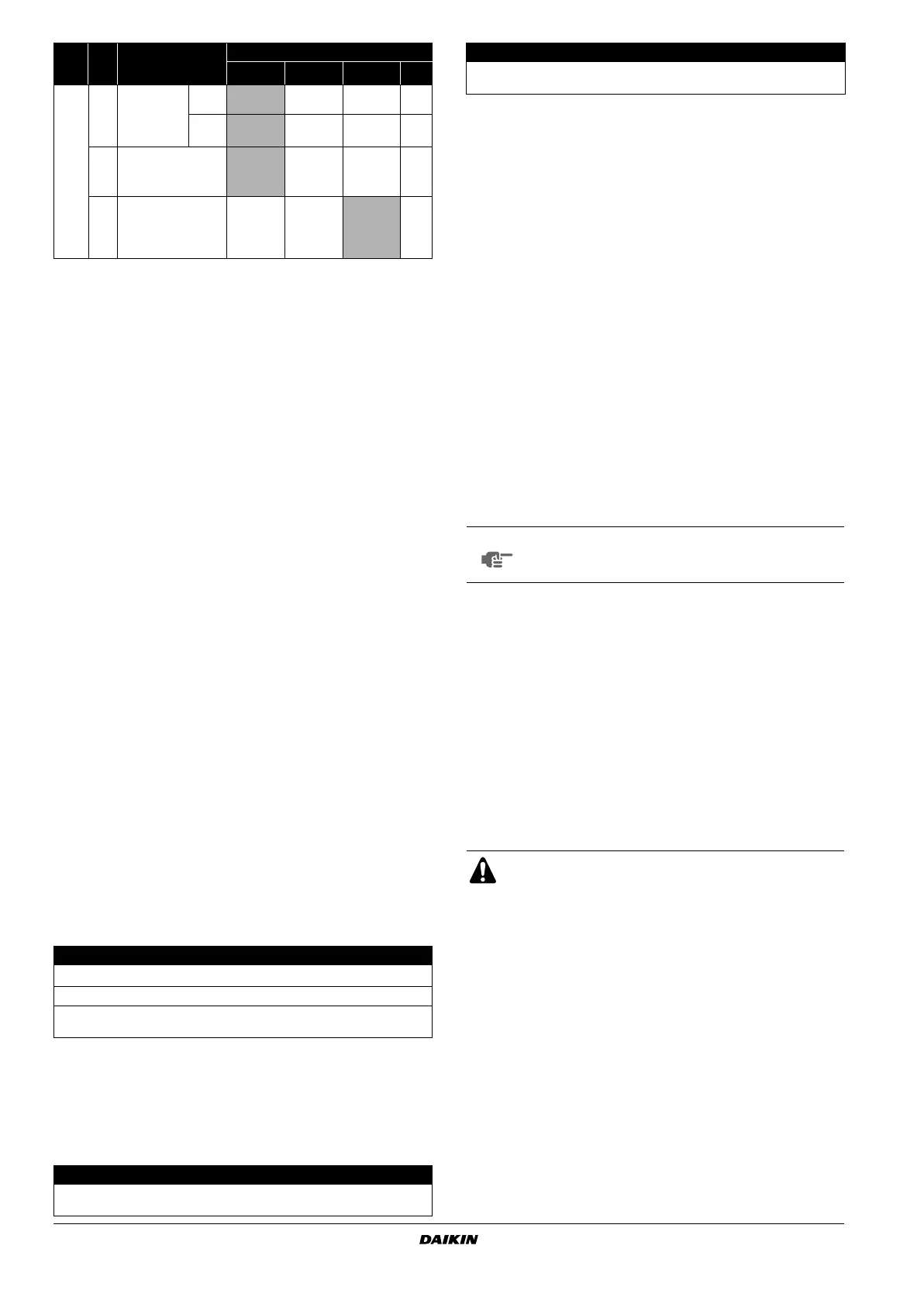
13
(23)
0
Setting for air outlet
velocity
This setting is to be
changed in function
of ceiling height.
other
models
≤2.7 m >2.7 ≤3.0 m >3.0 ≤3.5 m —
FXFQ125
only
≤3.2 m >3.2 ≤3.6 m >3.6 ≤4.2 m —
1
Selection for air flow direction
This setting is to be changed
when blocking pad optional kit
is used.
4-way flow 3-way flow — —
4
Airflow direction range setting
This setting is to be changed
when range of swing flap
movement needs to be
changed.
Upper Medium Lower —
Note 1 :
Setting is carried out in the group mode, however, if the mode number inside parentheses is selected,
indoor units can also be set individually.
Note 2 :
Factory settings of the Second code No. are marked in grey backgrounds.
Note 3 :
Only use in combination with optional remote sensor or when setting 10-2-03 is used.
Note 4 :
If group control is selected and remocon sensor is to be used, then set 10-6-02 & 10-2-03.
Note 5 :
If setting 10-6-02 + 10-2-01 or 10-2-02 or 10-2-03 are set at the same time, then setting 10-2-01,
10-2-02 or 10-2-03 have priority.
Note 6 :
If setting 10-6-01 + 10-2-01 or 10-2-02 or 10-2-03 are set at the same time, then setting for group
connection, 10-6-01 has priority and for individual connection, 10-2-01, 10-2-02 or 10-2-03 have priority.
Note 7 :
More settings for Differential automatic change over temperatures are:
Second code No.
05 4°C
06 5°C
07 6°C
08 7°C
1 Remote controller PC board
2 Factory setting
3 Only one remote controller needs to be changed
Wire specification Sheathed vinyl cord or cable (2 wire)
Gauge
0.75-1.25 mm
2
Length Max. 100 m
External terminal
Contact that can ensure the minimum applicable load
of 15 V DC, 1 mA
1 Input A
Forced off on/off operation
Input "on" stops operation
input off → on: turns on the unit
(impossible by remote controllers)
Mode
No.
(Note 1)
First
code
No.
Description of setting
Second code No. (Note 2)
01 02 03 04
Input "off" enables control
input on → off: turns off the unit
(by remote controller)
1 Second code No.
2 Mode No.
3 First code No.
4 Field set mode
NOTE
When performing field settings or test operation
without attaching the decoration panel, do not touch
the drain pump. This may cause electric shock.
1 Drain pumping device (built-in) drain water is removed from the
room during cooling
2 Air flow flap (at air outlet)
3 Air outlet
4 Remote controller
5 Suction grille
6 Air filter (inside suction grille)
CAUTION
Forced off on/off operation
EN3P320142-1F.book Page 9 Tuesday, October 3, 2017 2:46 PM
Bekijk gratis de handleiding van Daikin FXFQ100AVEB, stel vragen en lees de antwoorden op veelvoorkomende problemen, of gebruik onze assistent om sneller informatie in de handleiding te vinden of uitleg te krijgen over specifieke functies.
Productinformatie
| Merk | Daikin |
| Model | FXFQ100AVEB |
| Categorie | Niet gecategoriseerd |
| Taal | Nederlands |
| Grootte | 2934 MB |


