Handleiding
Je bekijkt pagina 20 van 28
14 Electrical installation
Installation and operation manual
20
FXDA10~63A2VEB
VRV system air conditioner
3P599562-1C – 2022.02
Component Class
10 15~32 40 50+63
Recommended field
fuse
6A
Residual current
device
Must comply with applicable legislation
(a)
MCA=Minimum circuit ampacity. Stated values are maximum
values (see electrical data of indoor unit for exact values).
14.2 To connect the electrical wiring to
the indoor unit
NOTICE
▪ Follow the wiring diagram (delivered with the unit,
located at the inside of the service cover).
▪ For instructions on how to connect the optional
equipment, see the installation manual delivered with
the optional equipment.
▪ Make sure the electrical wiring does NOT obstruct
proper reattachment of the service cover.
It is important to keep the power supply and the transmission wiring
separated from each other. In order to avoid any electrical
interference the distance between both wirings should ALWAYS be
at least 50mm.
NOTICE
Be sure to keep the power line and transmission line apart
from each other. Transmission wiring and power supply
wiring may cross, but may NOT run parallel.
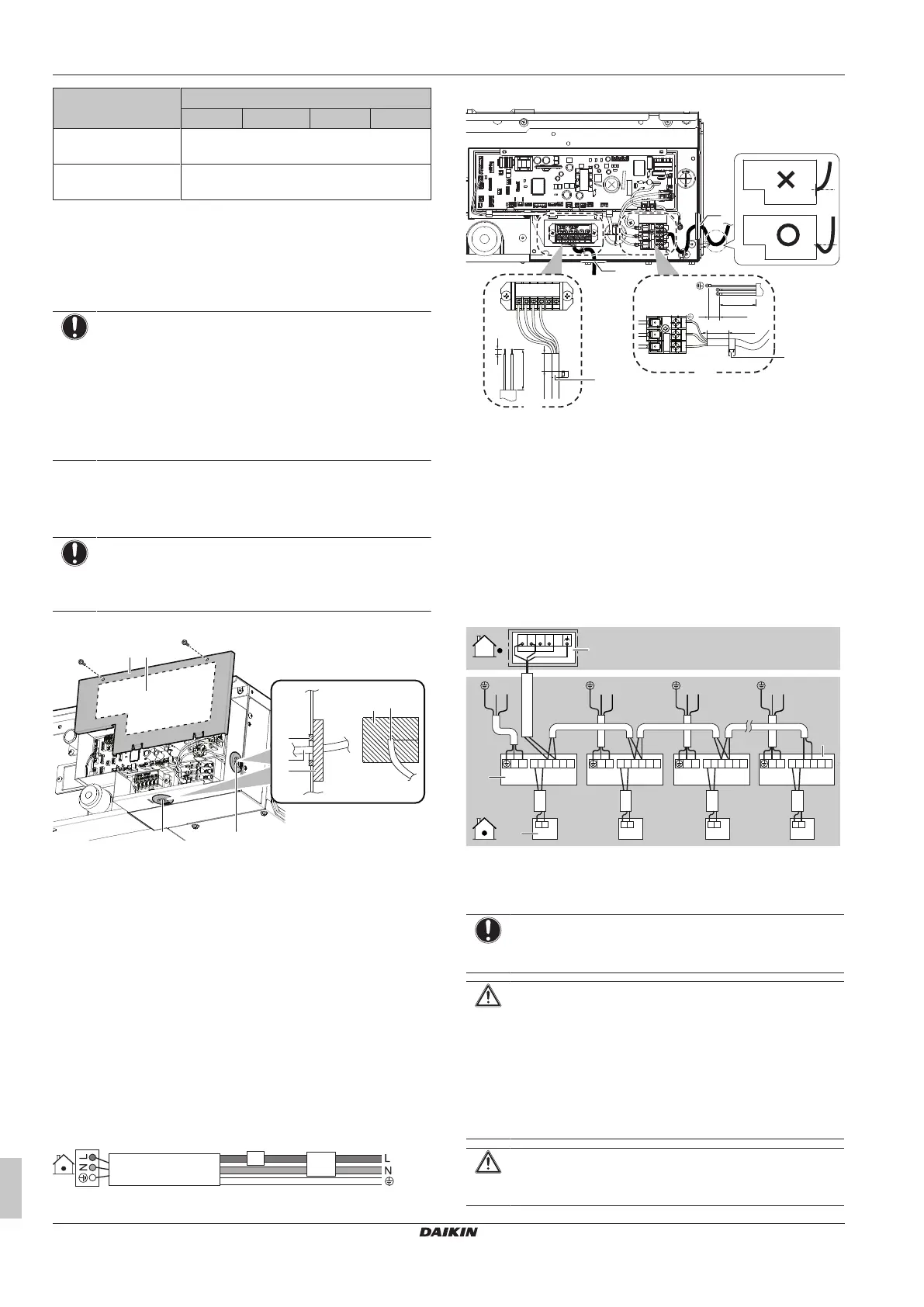
1 Remove the service cover.
BA
f
g
f
e
g
a b
c d
A Inside the unit
B Outside the unit
a Service cover
b Wiring diagram
c Connection of transmission and user interface wiring
d Connection of power supply
e Opening for cables
f Wire
g Sealing material (accessory)
2 User interface cable: Route the cable through the frame,
connect the cable to the terminal block (symbols P1, P2).
3 Transmission cable: Route the cable through the frame,
connect the cable to the terminal block (make sure the symbols
F1, F2 match with the symbols on the outdoor unit). Bundle the
transmission cable with the user interface cable and fix them
with a tie wrap on the wiring fixture.
4 Power supply cable: Route the cable through the frame and
connect the cable to the terminal block (L, N, earth). Fix the
cable with a tie wrap on the wiring fixture.
a
b
a Circuit breaker
b Residual current device
a
a
L
N
10~15
70~90
10~20
d
10~15
70~90
7
P1P2 F1 F2
d
c
b
a Opening for cables
b Transmission and user interface wiring
c Power supply wiring
d Large tie wrap (accessory)
X Not allowed
O Allowed
5 Wrap the cables with the sealing material (accessory) to
prevent water from entering the unit. Seal all gaps to prevent
small animals from entering the system.
6 Reattach the service cover.
Complete system example
1 user interface controls 1 indoor unit.
LN LN LN
P
1
P
2
P
1
P
2
P
1
P
2
P
1
P
2
P
1
P
2
F
1
F
2
T
1
T
2
P
1
P
2
F
1
F
2
T
1
T
2
P
1
P
2
F
1
F
2
T
1
T
2
P
1
P
2
F
1
F
2
T
1
T
2
N L
d
c
b
LN
N L N L N L
TO OUT/D
TO IN/D
a
a Outdoor unit
b Indoor unit
c User interface
d Most downstream indoor unit
NOTICE
For the use of group control and related limitations refer to
manual of outdoor unit.
CAUTION
▪ Each indoor unit has to be connected to a separate
user interface. Only a safety system compatible remote
controller can be used as the user interface. See
technical data sheet for remote controller compatibility
(e.g. BRC1H52/82*).
▪ The user interface has to be put in the same room as
the indoor unit. For details, please refer to the
installation and operation manual of the user interface.
CAUTION
In case shielded wire is used, connect the shielding to the
outdoor unit side only.
Bekijk gratis de handleiding van Daikin FXDA15A2VEB, stel vragen en lees de antwoorden op veelvoorkomende problemen, of gebruik onze assistent om sneller informatie in de handleiding te vinden of uitleg te krijgen over specifieke functies.
Productinformatie
| Merk | Daikin |
| Model | FXDA15A2VEB |
| Categorie | Airco |
| Taal | Nederlands |
| Grootte | 4251 MB |


