Daikin EWYQ-BAWP handleiding
Handleiding
Je bekijkt pagina 14 van 52
Installation and operation manual
9
EWAQ016~064BAW + EWYQ016~064BAW
Packaged air-cooled water chiller
4PW70082-1E – 2016.12
Make sure the unit is installed level on a sufficiently strong base
to prevent vibration and noise.
The height of the foundation must at least be 150 mm from the
floor.
In heavy snowfall areas, this height should be increased
dependant on the installation place and condition.
The unit must be installed on a solid longitudinal foundation
(steelbeam frame or concrete) and make sure the base under
the unit is larger than the grey marked area in figure 7:
1 Hole for foundation bolt
2 Inner dimension of the base
3 Distance between foundation bolt holes
4 Depth of unit
5 Outer dimension of the base
6 Longitudinal foundation dimension
7 Distance between foundation bolt holes
Fasten the unit in place using foundation
bolts M12. It is best to screw in the
foundation bolts until their length remains
20 mm above the foundation surface.
8.8. Drain work
Prepare a water drainage channel around the foundation to
drain waste water from around the unit.
During heating operation and when the outdoor temperatures
are negative, the drained water from the unit will freeze up. If the
water drainage is not taken care of, the area around the unit
might be very slippery.
8.9. Water piping work
8.9.1. Preparing the water piping work
The units have a water inlet and water outlet for connection to a water
circuit. This circuit must be provided by a licensed technician and
must comply with all applicable legislations.
Before continuing the installation of the unit, beware of the following
points:
Two shut-off valves are delivered with the unit. To facilitate
service and maintenance, install as shown in "8.9.4. Installing
the shut-off valve kit" on page 11.
Drain taps must be provided at all low points of the system to
permit complete drainage of the circuit. A drain valve is provided
inside the unit.
Air purges must be provided at all high points of the system. The
vents should be located at points which are easily accessible for
servicing. An automatic air purge is provided inside the unit.
Check that this air purge valve is not tightened too much so that
automatic release of air in the water circuit remains possible.
Refer to the "[E-04] Pump only operation (air purge function)" on
page 24.
Take care that the components installed in the field piping can
withstand the water pressure (maximum 3 bar + static pressure
of the pump).
- For units with a standard pump installed (EWA/YQ*BAWP),
refer to figure 14 (external static pressure and water flow)
- For units with an optional high static pump installed
(EWA/YQ*BAWH), refer to figure 15 (external static pressure
and water flow)
- For units without pump (EWA/YQ*BAWN), refer to figure 16
(pressure drop and water flow)
The maximum water piping temperature is 50°C according to
safety device setting.
Always use materials which are compatible with the water used
in the system and with the materials used in the unit.
(The unit piping fittings are made of brass, the plate heat
exchangers are made of stainless steel 316 plates brazed
together with copper and the optional pump housing is made of
cast iron.)
Select piping diameter in relation to required water flow and
available external static pressure (ESP) of the pump.
The recommended water piping diameter is:
- for units 016~032: 1-1/4"
- for units 040~064: 2"
The minimum required water flow for the unit operation is shown
in the following table.
When the water flow is lower than this minimum value,
eventually flow error A6 will be displayed and the operation of
the unit will be stopped.
NOTICE
A forklift can not be used!
NOTICE
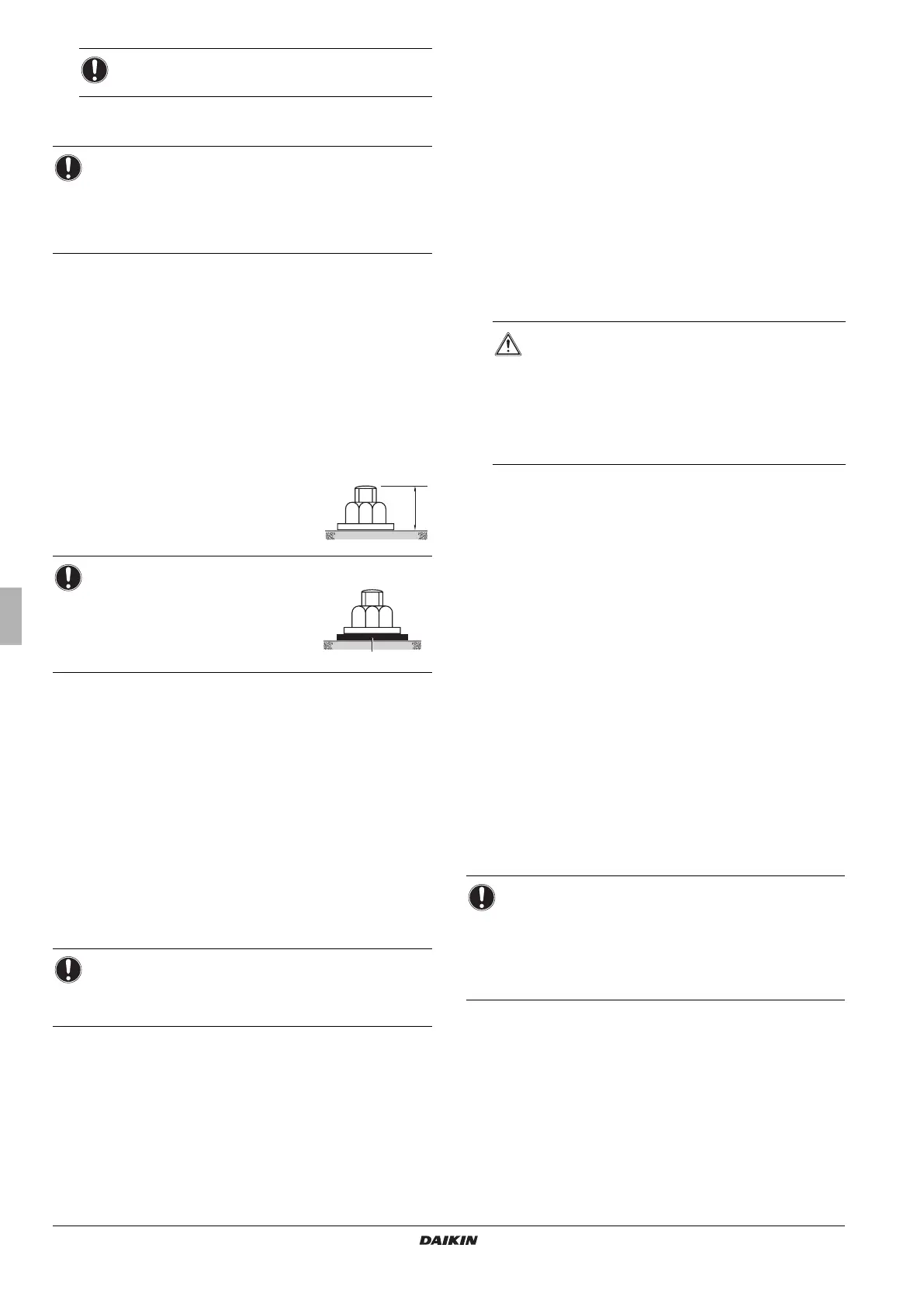
When the installation height of the unit needs to be
increased, do not use stands to only support the corners
as shown in figure 6.
X Not allowed
O Allowed (units: mm)
NOTICE
When installed in a corrosive
environment, use a nut with
plastic washer (1) to protect the
nut tightening part from rust.
NOTICE
The unit is only to be used in a closed water system.
Application in an open water circuit can lead to excessive
corrosion of the water piping.
20 mm
1
WARNING
For correct operation of the system, a regulating
valve must be installed in the water system. The
regulating valve is to be used to regulate the
water flow in the system (field supply).
Selecting a flow outside the curves can cause
malfunction or damage to the unit. Also refer to
the table "Technical specifications" on page 3.
EWA/YQ016 + 021 = 23 l/min
EWA/YQ025 + 032 = 36 l/min
EWA/YQ040 = 57 l/min
EWA/YQ050 + 064 = 72 l/min
NOTICE
It is strongly recommended to install an additional filter on
the water circuit. Especially to remove metallic particles
from the field water piping, it is advised to use a magnetic
or cyclone filter which can remove small particles. Small
particles can damage the unit and will not be removed by
the standard filter of the unit.
4PWEN70082-1E_2016_12.book Page 9 Wednesday, December 7, 2016 2:18 PM
Bekijk gratis de handleiding van Daikin EWYQ-BAWP, stel vragen en lees de antwoorden op veelvoorkomende problemen, of gebruik onze assistent om sneller informatie in de handleiding te vinden of uitleg te krijgen over specifieke functies.
Productinformatie
| Merk | Daikin |
| Model | EWYQ-BAWP |
| Categorie | Niet gecategoriseerd |
| Taal | Nederlands |
| Grootte | 9272 MB |


