Daikin ERSQ016AAV1 handleiding
Handleiding
Je bekijkt pagina 20 van 24
Installation manual
17
ERSQ+ERRQ011~016AAV1+Y1
Outdoor unit for air to water heat pump
4PW49635-1C
11. TEST OPERATION AND FINAL CHECK
11.1. Final check
■ Be sure to perform a test run.
■ To protect the compressor, make sure to turn on the power
supply 6 hours before starting operation.
■ Be sure to fully open the liquid-side and gas-side stop valves. If
you operate the unit with stop valves closed, the compressor will
break down.
■ Never leave the unit unattended with an open front panel during
test run.
■ After installation, perform the test operation.
Unless the test operation is performed, the error code "U3" is
shown on the remote controller and the unit cannot be operated.
■ During tests never pressurize the appliances with a pressure
higher than the maximum allowable pressure (as indicated on
the nameplate of the unit).
■ Provide a logbook.
In accordance with the relevant national and international
regulations it may be neccesary to provide a logbook with the
equipment containing at least:
- info on maintenance,
- repair work,
- results of tests,
- stand-by periods,
- ...
In Europe, EN378 provides the neccesary guidance for this
logbook.
11.2. Test run
Perform the test run in accordance with the indoor installation manual
to ensure that all functions and parts are working properly.
12. MAINTENANCE AND SERVICING
12.1. Service precautions
Caution when performing service to inverter equipment
■ Do not touch live parts for 10 minutes after the power supply is
turned off because of high voltage risk.
■ Additionally, measure the points as shown in figure 10 with a
tester and confirm that the voltage of the capacitor in the main
circuit is no more than 50 V DC.
■ Make sure that the power supply is turned off before performing
the maintenance work. The heater of the compressor may
operate even in stop mode.
■ Please note that some sections of the electric component box
are extremely hot.
■ In order to prevent damage to the PCB, first eliminate static
electricity by touching a metal part (e.g. stop valve) with your
hand. Then pull out the connector.
■ After measuring the residual voltage, pull out the outdoor fan
connector.
■ Make sure you do not touch a conductive section.
■ The outdoor fan may rotate due to strong backblow wind,
causing the capacitor to charge. This may result in an electric
shock.
After maintenance, make sure the outdoor fan connector is
connected again. Otherwise, the unit may break down.
12.2. Service mode operation
If required, carry out any service mode operation according to the
following instructions. Refer to the service manual for more details.
Setting the mode
The set mode can be changed with the button according
to the following procedure:
■ For setting mode 1: Press the button once, the
H1P LED is off
x.
■ For setting mode 2: Press the button for
5 seconds, the H1P LED is on
w.
If the H1P LED is blinking c and the button is pushed
once, the setting mode will change to setting mode 1.
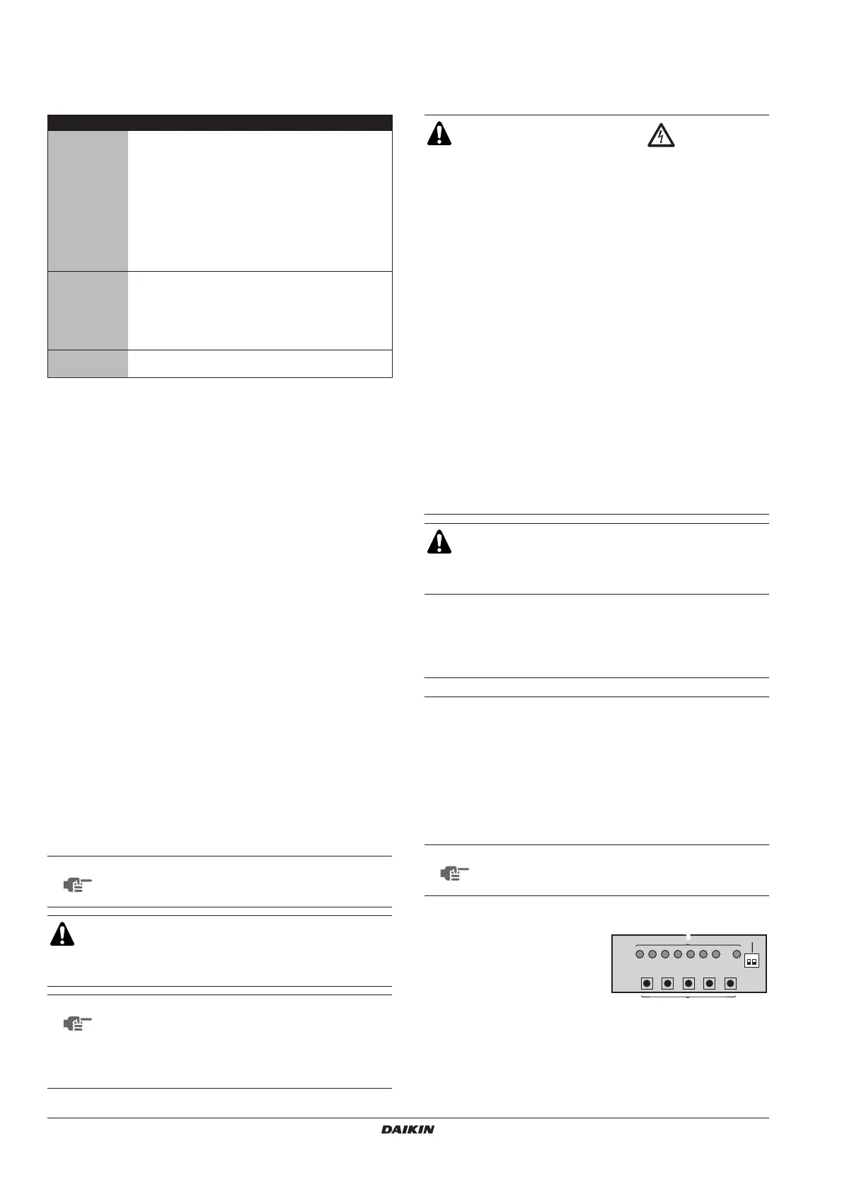
Location of the dip switches, LEDs and buttons
LED state
Throughout the manual the state of the LEDs is indicated as follows:
Items to check
Electrical wiring
Inter-unit wiring
Earth wire
■ Is the wiring as mentioned on the wiring diagram?
Make sure no wiring has been forgotten and that
there are no missing phases or reverse phases.
■ Is the unit properly earthed?
■ Is the wiring between units connected in series
correct?
■ Are any of the wiring attachment screws loose?
■ Is the insulation resistance at least 1 MΩ?
- Use a 500 V mega-tester when measuring
insulation.
- Do not use a mega-tester for low-voltage circuits.
Refrigerant
piping
■ Is the size of the piping appropriate?
■ Is the insulation material for the piping attached
securely?
Are both the liquid and gas pipes insulated?
■ Are the stop valves for both the liquid side and the
gas side open?
Extra
refrigerant
■ Did you write down the extra refrigerant and the
refrigerant piping length?
NOTE
After turning on the power supply, the unit can not be
started until the H2P initialisation led goes off
(maximum 12 minutes).
WARNING
Live parts can be easily touched by accident.
Never leave the unit unattended during installation or
servicing when the service panel is removed.
NOTE
Note that during the first running period of the unit,
required power input may be higher than stated on the
nameplate of the unit. This phenomenon originates
from the compressor that needs elapse of a 50 hours
run in period before reaching smooth operation and
stable power consumption.
WARNING: ELECTRIC SHOCK
Play it safe!
Touch a metal part by hand (such as the stop valve) in
order to eliminate static electricity and to protect the PCB
before performing service.
NOTE
If you get confused in the middle of the setting process,
push the button. Then it returns to setting
mode 1 (H1P LED is off).
1
Led H1P~H8P
2
Push button switches BS1~BS5
3
DIP switches
(do not use or change)
x
OFF
w
ON
c
blinking
BS1 MODE
BS1 MODE
BS1 MODE
BS1 MODE
BS1 MODE
1
3
2
3
Bekijk gratis de handleiding van Daikin ERSQ016AAV1, stel vragen en lees de antwoorden op veelvoorkomende problemen, of gebruik onze assistent om sneller informatie in de handleiding te vinden of uitleg te krijgen over specifieke functies.
Productinformatie
| Merk | Daikin |
| Model | ERSQ016AAV1 |
| Categorie | Niet gecategoriseerd |
| Taal | Nederlands |
| Grootte | 3831 MB |


