Daikin ERA250AMYFB handleiding
Handleiding
Je bekijkt pagina 41 van 48
22 Troubleshooting
Installation and operation manual
41
ERA200~300AMYFB
Inverter outdoor unit for AHU option kit and air curtains
4P780153-1 – 2024.07
with a tester and confirm that the voltage of the capacitor in the
main circuit is less than 50VDC. If the voltage measured is still
higher than 50VDC, discharge the capacitors in a safe manner
by using a dedicated capacitor discharge pen to avoid
possibility of sparking.
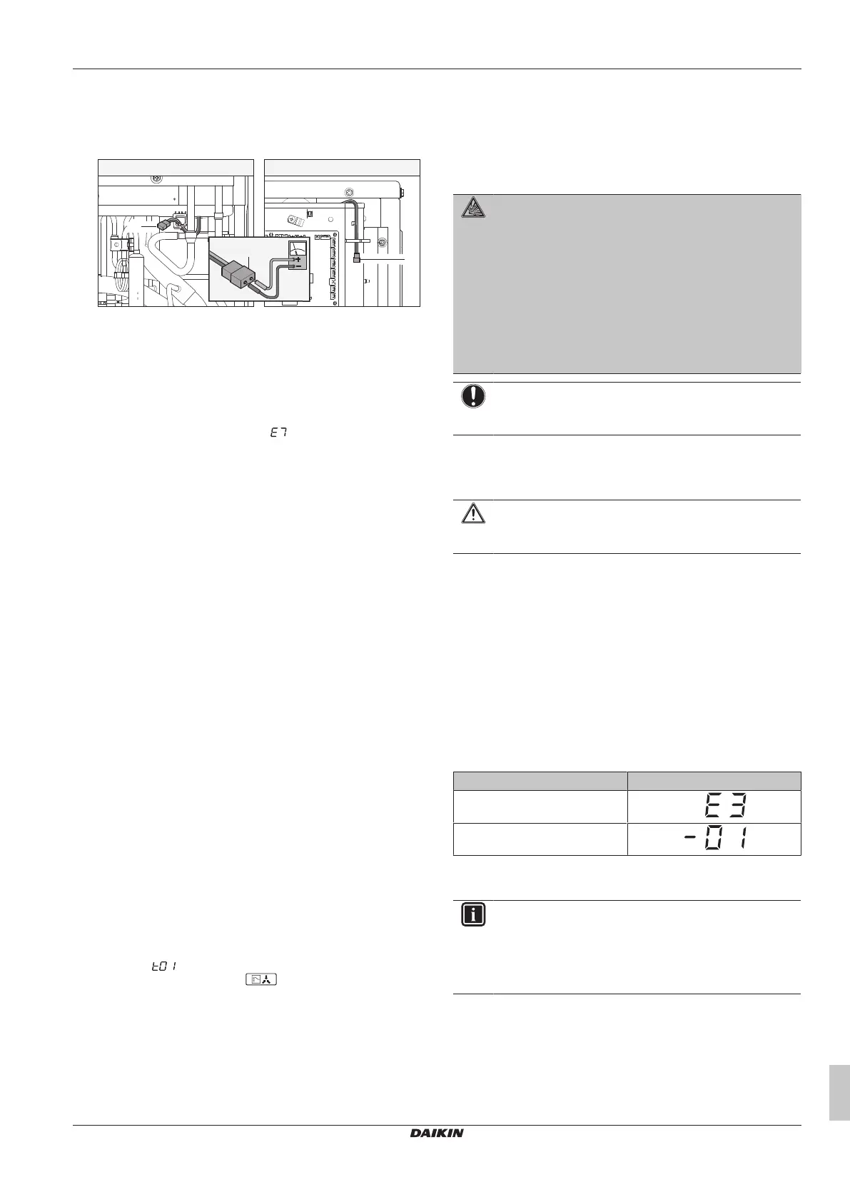
ERA200 ERA250+300
a
a
a
a Connector for capacitor voltage check
3 Pull out junction connectors X1A, X2A for the fan motors in the
outdoor unit before starting service operation on the inverter
equipment. Be careful NOT to touch the live parts. (If a fan
rotates due to strong wind, it may store electricity in the
capacitor or in the main circuit and cause electrical shock.)
4 After the service is finished, plug the junction connector back in.
Otherwise the malfunction code will be displayed on the
user interface or on the outdoor unit 7‑segment display and
normal operation will NOT be performed.
For details refer to the wiring diagram labelled on the back of the
switch box/service cover.
Pay attention to the fan. It is dangerous to inspect the unit while the
fan is running. Make sure to turn off the main switch and to remove
the fuses from the control circuit located in the outdoor unit.
21.2 Checklist for yearly maintenance of
the outdoor unit
Check the following at least once a year:
▪ Heat exchanger
The heat exchanger of the outdoor unit can get blocked up due to
dust, dirt, leaves, etc. It is recommended to clean the heat
exchanger yearly. A blocked heat exchanger can lead to too low
pressure or too high pressure leading to worse performance.
21.3 About service mode operation
Refrigerant recovery operation/vacuuming operation is possible by
applying setting [2‑21]. Refer to "18.1Making field settings"[436] for
details how to set mode2.
When vacuuming/recovery mode is used, check very carefully what
should be vacuumed/recovered before starting. See installation
manual of the indoor unit for more information about vacuuming and
recovery.
21.3.1 To use vacuum mode
1 When the unit is at standstill, set the unit in [2‑21]=1.
Result: When confirmed, the indoor and outdoor unit expansion
valves will fully open. At that moment the 7‑segment display
indication= and the user interface of the indoor unit indicate
TEST (test operation) and (external control) and the
operation will be prohibited.
2 Evacuate the system with a vacuum pump.
3 Press BS3 to stop vacuuming mode.
21.3.2 To recover refrigerant
This should be done with a refrigerant recovery unit. Follow the
same procedure as for vacuuming method.
DANGER: RISK OF EXPLOSION
Pump down – Refrigerant leakage. If you want to pump
down the system, and there is a leak in the refrigerant
circuit:
▪ Do NOT use the unit's automatic pump down function,
with which you can collect all refrigerant from the
system into the outdoor unit. Possible consequence:
Self-combustion and explosion of the compressor
because of air going into the operating compressor.
▪ Use a separate recovery system so that the unit's
compressor does NOT have to operate.
NOTICE
Make sure to NOT recover any oil while recovering
refrigerant. Example: By using an oil separator.
22 Troubleshooting
CAUTION
See "2 Specific installer safety instructions" [4 5] to make
sure troubleshooting complies with all safety regulations.
22.1 Solving problems based on error
codes
In case of a displayed malfunction code, perform correcting actions
as explained in the malfunction code table.
After correcting the abnormality, press BS3 to reset the malfunction
code and retry operation.
The malfunction code which is displayed on the outdoor unit will
indicate a main malfunction code and a sub code. The sub code
indicates more detailed information about the malfunction code. The
malfunction code will be displayed intermittent.
Example:
Code Example
Main code
Sub code
With an interval of 1second, the display will switch between main
code and sub code.
INFORMATION
See the service manual for:
▪ The complete list of error codes
▪ A more detailed troubleshooting guideline for each
error
Bekijk gratis de handleiding van Daikin ERA250AMYFB, stel vragen en lees de antwoorden op veelvoorkomende problemen, of gebruik onze assistent om sneller informatie in de handleiding te vinden of uitleg te krijgen over specifieke functies.
Productinformatie
| Merk | Daikin |
| Model | ERA250AMYFB |
| Categorie | Ventilator |
| Taal | Nederlands |
| Grootte | 8144 MB |


