Daikin EKEXVA400 handleiding
Handleiding
Je bekijkt pagina 31 van 36
19 Technical data
Installation and operation manual
31
EKEACBVE + EKEXVA50~500
Option kit for combination of Daikin outdoor units with field-
supplied air handling units
4P724517-1 – 2023.06
INFORMATION
See the service manual for:
▪ The complete list of error codes
▪ A more detailed troubleshooting guideline for each
error
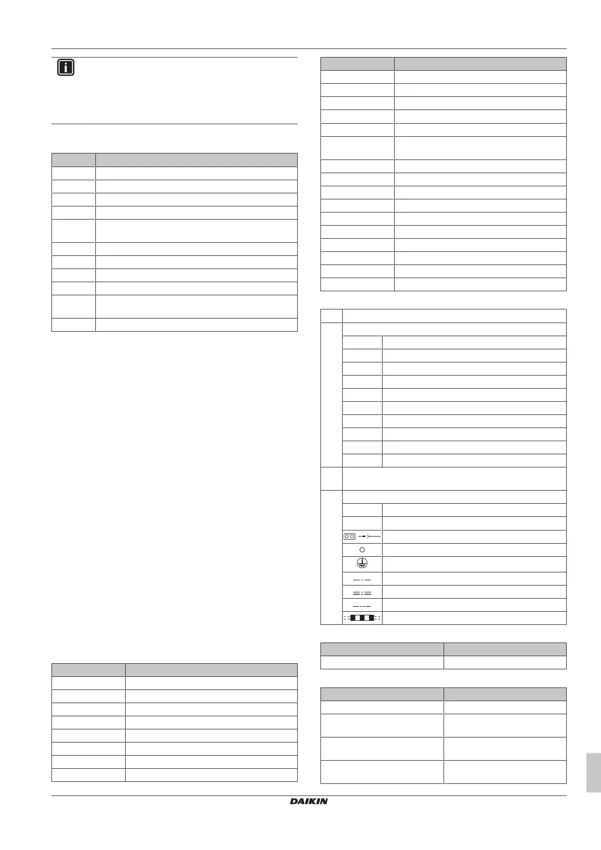
18.1.1 Error codes: Overview
Code Description
A0 External protection device activated
A1 Malfunction of EKEA main PCB A1P
A9 Malfunction of electronic expansion valve
AJ Capacity setting error
C1 Failure of transmission (between indoor unit PCB and
sub PCB)
C4 Malfunction of liquid pipe thermistor for heat exchanger
C5 Malfunction of gas pipe thermistor for heat exchanger
C9 Malfunction of suction air thermistor
CA Malfunction of discharge air thermistor
CJ Room temperature thermistor in remote controller
abnormality
UJ-37 Airflow rate below the legal limit
18.2 Symptom: The AHU heat
exchanger is freezing up
▪ Check if the liquid thermistor (R2T) is put on the correct location.
The thermistor must be put on the coldest location.
▪ Check if the thermistor has come loose. The thermistor must be
fixed.
▪ The air handling unit fan is not operating continuously.
When the outdoor unit stops operating, the air handling unit fan
must continue operation to melt the ice that was accumulated
during outdoor unit operation.
Ensure that the air handling unit fan keeps operating.
For other issues, see the service manual.
19 Technical data
▪ A subset of the latest technical data is available on the regional
Daikin website (publicly accessible).
▪ The full set of latest technical data is available on the Daikin
Business Portal (authentication required).
19.1 Wiring diagram
The wiring diagram is delivered with the control box, located at the
inside of the cover.
Legend
Part Description
A1P PCB (main)
A2P PCB (relay)
A3P PCB (converter)
A4P PCB (demand)
A5P PCB (power supply)
F1U Field fuse
F1U (A1P) Fuse T 3.15A 250V
F1U (A2P) Fuse T 6.3A 250V
Part Description
K1R Magnetic relay (error state)
K2R Magnetic relay (fan ON/OFF)
K3R Magnetic relay (inverter operation)
K4R Magnetic relay (defrost)
K5R Magnetic relay (R32 alarm)
K8R Magnetic relay (feedback connection relay
PCB to main PCB)
Q1DI Earth leakage circuit breaker
R1T Thermistor (suction air)
R2T Thermistor (liquid)
R3T Thermistor (gas)
R4T Thermistor (discharge air)
X1M Terminal block
X2M Terminal block
X3M Terminal block
Y1E Electronic expansion valve
Z*C Noise filter (ferrite core)
Notes
1 Use copper conductors only.
2 Colours:
BLK Black
BLU Blue
BRN Brown
GRN Green
GRY Grey
ORG Orange
PNK Pink
RED Red
WHT White
YLW Yellow
3 Mandatory for R32 applications, short-circuited if not used for
R410A applications.
4 Symbols:
L Live
N Neutral
Connector
Wire clamp
Protective earth (screw)
Separate component
Optional accessory
Wiring depending on control type
Field wiring
Position in switch box
English Translation
Position in switch box Position in switch box
Translation of text on wiring diagram
English Translation
0-10 V DC input signal 0-10VDC input signal
16 V DC digital input AHU error
(NO)
16VDC digital input AHU error
(normally open)
16 V DC digital input cooling/
heating (NC)
16VDC digital input cooling/
heating (normally closed)
16 V DC digital input ON/OFF
(NO)
16VDC digital input ON/OFF
(normally open)
Bekijk gratis de handleiding van Daikin EKEXVA400, stel vragen en lees de antwoorden op veelvoorkomende problemen, of gebruik onze assistent om sneller informatie in de handleiding te vinden of uitleg te krijgen over specifieke functies.
Productinformatie
| Merk | Daikin |
| Model | EKEXVA400 |
| Categorie | Niet gecategoriseerd |
| Taal | Nederlands |
| Grootte | 5715 MB |


