Daikin EKEXVA400 handleiding
Handleiding
Je bekijkt pagina 12 van 36
11 About the system
Installation and operation manual
12
EKEACBVE + EKEXVA50~500
Option kit for combination of Daikin outdoor units with field-
supplied air handling units
4P724517-1 – 2023.06
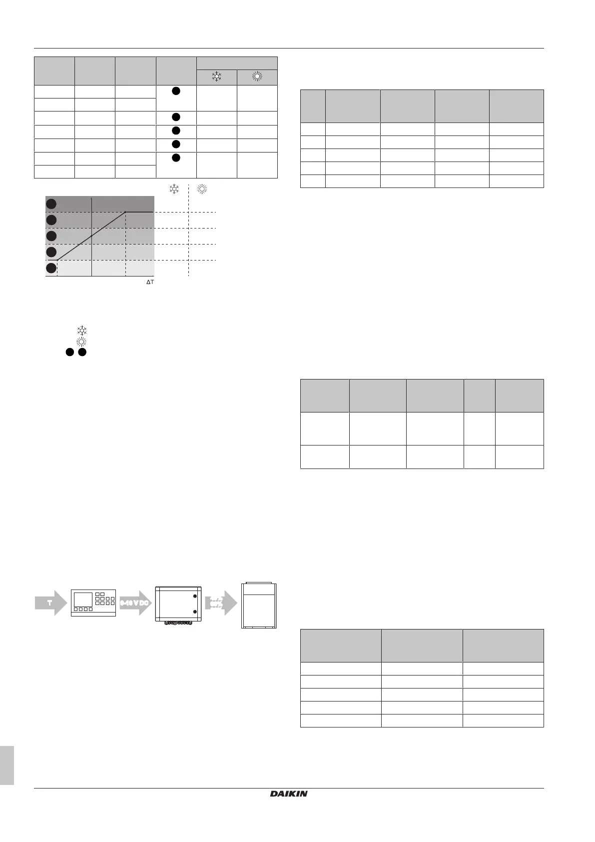
T ΔT V Capacity
level
Capacity request
20°C –4°C 0V
1
↓↓ ↑↑
21°C –3°C 0V
22.5°C –1.5°C 2.5V
2
↓ ↑
24°C 0°C 5V
3
→ →
25.5°C 1.5°C 7.5V
4
↑ ↓
27°C 3°C 10V
5
↑↑ ↓↓
28°C 4°C 10V
+3°C–3°C 0°C
↓↓
↓
→
↑
↑↑
V
0 V
10 V
1
5
2
3
4
↓↓
↓
→
↑
↑↑
T Actual measured temperature
ΔT [Actual measured temperature]–[Target room
temperature]
V Voltage output of controller (field supply).
Cooling capacity request
Heating capacity request
1
~
5
Capacity level
↑↑ Cooling/heating capacity strongly increases
↑ Cooling/heating capacity increases
→ Unit keeps operating at same capacity level
↓ Cooling/heating capacity decreases
↓↓ Cooling/heating capacity strongly decreases
11.2.2 Y control: Operation with fixed Te/Tc
temperature control
A fixed target evaporating temperature (T
e
) / condensing
temperature (T
c
) can be set by the customer via the field settings of
the control box: see 13(23)–14 and 13(23)–15 in "16.2 Field
settings" [4 29]. This system does not require a specific external
controller.
11.2.3 W control: Operation with 0-10VDC
capacity control
For W control, a controller (field supply) needs to be connected to
the EKEA control box. The controller will generate a 0–10 V DC
signal that will be used by the EKEA control box for the capacity
control of the system.
Contr.
EKEA
0-10 V DC0-10 V DC
0%
40%
60%
80%
100%
0%
40%
60%
80%
100%
TT
O/U
Contr. Controller (field supply)
EKEA Control box
O/U Outdoor unit
0%~100% Capacity control level sent to the outdoor unit via F1F2
0-10VDC Voltage signal
T Temperature
The system needs a controller (field supply) with a temperature
sensor. The temperature sensor can be used to control the following
temperatures:
▪ Suction air temperature of the air handling unit
▪ Room air temperature
▪ Discharge air temperature of the air handling unit
The EKEA control box will interpret the 0–10VDC signal according
to 5 steps. The correlation between the voltage input and the system
capacity is as follows:
Step Voltage
input
(a)
System
capacity
(b)
T
e
during
cooling
operation
T
c
during
heating
operation
1 0.8V 0% (OFF) — —
2 2.5V 40% 13.5°C 31°C
3 5V 60% 11°C 36°C
4 7.5V 80% 8.5°C 41°C
5 9.2V 100% 6°C 46°C
(a)
Voltages shown are the centre points of each step range.
(b)
The capacities mentioned in the table are not exact. The
compressor frequency can vary and will have an impact on the
system capacity.
▪ The system response to the 0–10VDC output from the controller
(field supply) is the same in cooling and heating operation. 10 V
means 100% system capacity in cooling and heating operation.
The controller will output a 0–10VDC signal based on ∆T (for the
definition of ∆T, see "11.2.1X control: Operation with 0-10 VDC
capacity control"[411]).
▪ In the table below an example is given.
▪ A ∆T of 4°C in cooling operation means that the controller (field
supply) needs to output 10 V, so that the cooling capacity will
be 100%.
▪ A ∆T of 4°C in heating operation means that the controller (field
supply) needs to output 0V, so that the heating capacity will be
0% (OFF).
Operation Target
temperature
Actual
measured
temperature
∆T Required
system
response
Cooling 24°C 28°C +4°C High
capacity
(10V)
Heating 24°C 28°C +4°C No capacity
(0V)
The response of the controller (field supply) must therefore be
inverted for cooling or heating operation.
11.2.4 Z control: Suction air control
This control method corresponds with standard Daikin suction air
control, as for normal VRV indoor units. The cooling/heating load is
determined based on the difference between the suction air
temperature and the setpoint.
The setpoint can be set in two different ways (see 11(21)–12 in
"16.2Field settings"[429]):
▪ Using a Daikin remote controller
▪ Using a 0-10VDC voltage signal on C1C2, according to the table
below:
Output from
controller [V] (field
supply)
Output capacity
level
T
set
[°C]
<1.5 Level 1 16
1.5≤x<3.5 Level 2 20
3.5≤x<6.5 Level 3 24
6.5≤x<8.5 Level 4 28
≥8.5 Level 5 32
Bekijk gratis de handleiding van Daikin EKEXVA400, stel vragen en lees de antwoorden op veelvoorkomende problemen, of gebruik onze assistent om sneller informatie in de handleiding te vinden of uitleg te krijgen over specifieke functies.
Productinformatie
| Merk | Daikin |
| Model | EKEXVA400 |
| Categorie | Niet gecategoriseerd |
| Taal | Nederlands |
| Grootte | 5715 MB |


