Daikin EKEXVA300 handleiding
Handleiding
Je bekijkt pagina 15 van 36
11 About the system
Installation and operation manual
15
EKEACBVE + EKEXVA50~500
Option kit for combination of Daikin outdoor units with field-
supplied air handling units
4P724517-1 – 2023.06
NOTICE
EKEA and EKEXVA are only parts of an air handling unit
system, complying with partial unit requirements of the
International Standard IEC 60335-2-40:2022. As such,
they must ONLY be connected to other units that have
been confirmed as complying to corresponding partial unit
requirements of this International Standard.
For installation of the air handling unit, see the air handling unit
installation manual.
The connected air handling unit must be designed for R410A or R32
applications.
In case of R32 systems that require safety measures, take the
following safety requirements into account:
▪ The air handling unit must be capable of supplying a minimum
airflow rate (Q
min
) for R32 safety. See "Figure 2"[43].
▪ Based on the conditioned space and the refrigerant amount, the
air handling unit should make sure it operates only in the
circulation airflow region (zone 1 in "Figure 2"[43]).
▪ The air handling unit must be equipped with supply and return air
isolation dampers.
AHU
c
b
g
f
d
a
e
AHU Air handling unit
a Conditioned space
b Outdoor air
c Exhaust air
d Supply air
e Extract air
f Supply damper
g Return damper
▪ The presence of dampers will allow to:
▪ Block the mixture of air and refrigerant going inside the building,
in the case of a leak;
▪ Establish a safe situation even though the compressor of the
VRV system would continue operating (e.g. defrost operation)
▪ The air handling unit should be able to output an additional error
(R32 safety related), in case the airflow rate supplied by the air
handling unit would drop below legal requirements. The air
handling unit must be able to check the current airflow rate and
compare it to the target airflow rate (Q
min
). See T5T6 specifications
in "11.3Operation signals"[413].
▪ When the fans of the air handling unit are stopped, the supply and
return isolation dampers need to close.
11.8 Connection ratio and heat
exchanger volume limitations
Connection ratio and heat exchanger volume limitations for pair
and multi applications
The connection ratio limit depends on the application.
For pair and multi applications, the lower limit of the connection ratio
is 75% in general. However, if more strict requirements for the heat
exchanger volume are satisfied, the lower limit of the connection
ratio is 65%.
See the manual of the outdoor unit for more detailed information.
For ERQ, these connection ratio limitations are NOT applicable.
Follow the combination table in "11.6.2 ERQ outdoor units" [4 14]
instead.
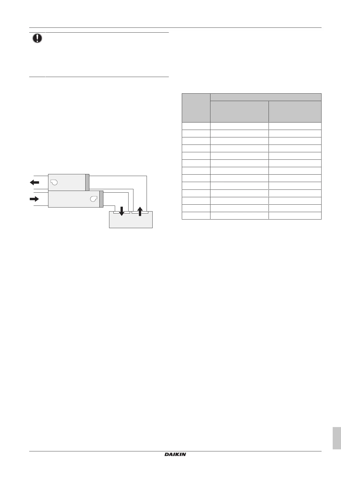
Heat exchanger volume limitations
The limitations for the volume of the AHU heat exchanger are shown
in the table below. In case of pair and multi applications, for
connection ratios between 65% and 75%, more strict limitations are
applicable.
For ERQ, follow the general limits.
Capacity
class
Minimum heat exchanger volume [dm³]
General limits (65%≤CR<75%)
Only for pair and multi
applications
50 0.95 1.09
63 1.02 1.18
80 1.42 1.64
100 1.51 1.74
125 1.98 2.29
140 2.54 2.94
200 3.02 3.49
250 3.97 4.58
300 4.53 5.23
350 5.48 6.32
400 6.04 6.97
450 6.99 8.07
500 7.55 8.72
CR Connection ratio
11.9 Master-slave configuration
In case of interlaced heat exchanger applications, a master-slave
configuration of EKEA can be used to reduce the number of cables
installed in the field. This is achieved by having a unique master
control box, which has all the external inputs/outputs (I/O), and
several slaves with a limited number of external I/O.
The master-slave function is activated via a field setting and can only
be used with X, Y and W control (all connected EKEAs must be set
to the same control type). Only one EKEA can be set as master, the
rest of the connected EKEAs must be set to slaves (for more
information see the field setting 14(24)-3 in "16.2 Field
settings" [4 29]). The maximum number of EKEAs that can be
connected together is limited to 10 (including the master EKEA).
The communication between the master and the slave EKEA control
boxes is achieved in part via P1P2 and in part via additional physical
wires. Therefore, to be able to use this functionality, a remote
controller must always be connected (see "11.4 Remote controller
for EKEA" [4 13]). The number of signals shared over the physical
cable depends on the system layout.
There are two main system layouts in case of interlaced heat
exchanger applications:
▪ Separate refrigerant circuits system
▪ Combined refrigerant circuit system
The figures below show examples of both systems. The systems
that are shown in the examples each have three outdoor units, but
this is just for illustrative purposes.
Bekijk gratis de handleiding van Daikin EKEXVA300, stel vragen en lees de antwoorden op veelvoorkomende problemen, of gebruik onze assistent om sneller informatie in de handleiding te vinden of uitleg te krijgen over specifieke functies.
Productinformatie
| Merk | Daikin |
| Model | EKEXVA300 |
| Categorie | Niet gecategoriseerd |
| Taal | Nederlands |
| Grootte | 5715 MB |


