D-Link DPS-PWR740AC handleiding
Handleiding
Je bekijkt pagina 54 van 69
DMS-3130 Series Layer 3 Stackable Managed Switch Hardware Installation Guide
54
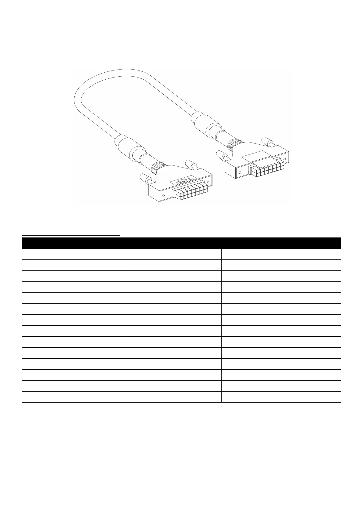
Redundant Power Supply (RPS) Cable
When connecting the Switch to an external Redundant Power Supply, an RPS cable is required. Please refer to this
product for cable pins matching. The following diagram and table show the standard RPS connector and its pin
assignments.
Figure B-3 RPS Cable for DPS-500A (14-pin Power Cable)
RPS Cable – 14 PIN Assignments:
Pin
Device
DPS-500A
1
Not Connected
GND
2
GND
N/C
3
GND
+12V
4
GND
+12V
5
GND
+12V
6
+12V
+12V
7
+12V
GND
8
+12V
N/C
9
Not Connected
N/C
10
Not Connected
RPS Power
11
RPS_Present
N/C
12
RPS_Power Good
N/C
13
Not Connected
PWR-Good
14
+12V
GND
Bekijk gratis de handleiding van D-Link DPS-PWR740AC, stel vragen en lees de antwoorden op veelvoorkomende problemen, of gebruik onze assistent om sneller informatie in de handleiding te vinden of uitleg te krijgen over specifieke functies.
Productinformatie
| Merk | D-Link |
| Model | DPS-PWR740AC |
| Categorie | Niet gecategoriseerd |
| Taal | Nederlands |
| Grootte | 10019 MB |


