D-Link DPS-PWR740AC handleiding
Handleiding
Je bekijkt pagina 21 van 69
DMS-3130 Series Layer 3 Stackable Managed Switch Hardware Installation Guide
21
LED
Description
active or blink amber when a 100/1000 Mbps port is active. The LED will be
off when there is no link or activity.
PoE LED (No. 1~24): The right LEDs of the above ports indicate power
supply status. This LED will light solid green when there is a PoE device
connected to the port and is receiving power from the port. This LED will
light amber to indicate an error state in power supply. The LED is off when
there is no power device connected to the port.
10G RJ45 Ports (No. 25~26): The left LED will light solid green when there
is a connection (or link) to a 2.5/5/10 Gbps Ethernet device; the right LED
will light solid amber when there is a connection (or link) to a 100/1000
Mbps Ethernet device on any of the RJ45 ports. The left LED will blink
green when a 2.5/5/10 Gbps port is active; the right LED will blink amber
when a 100/1000 Mbps port is active. The LED will be off when there is no
link or activity.
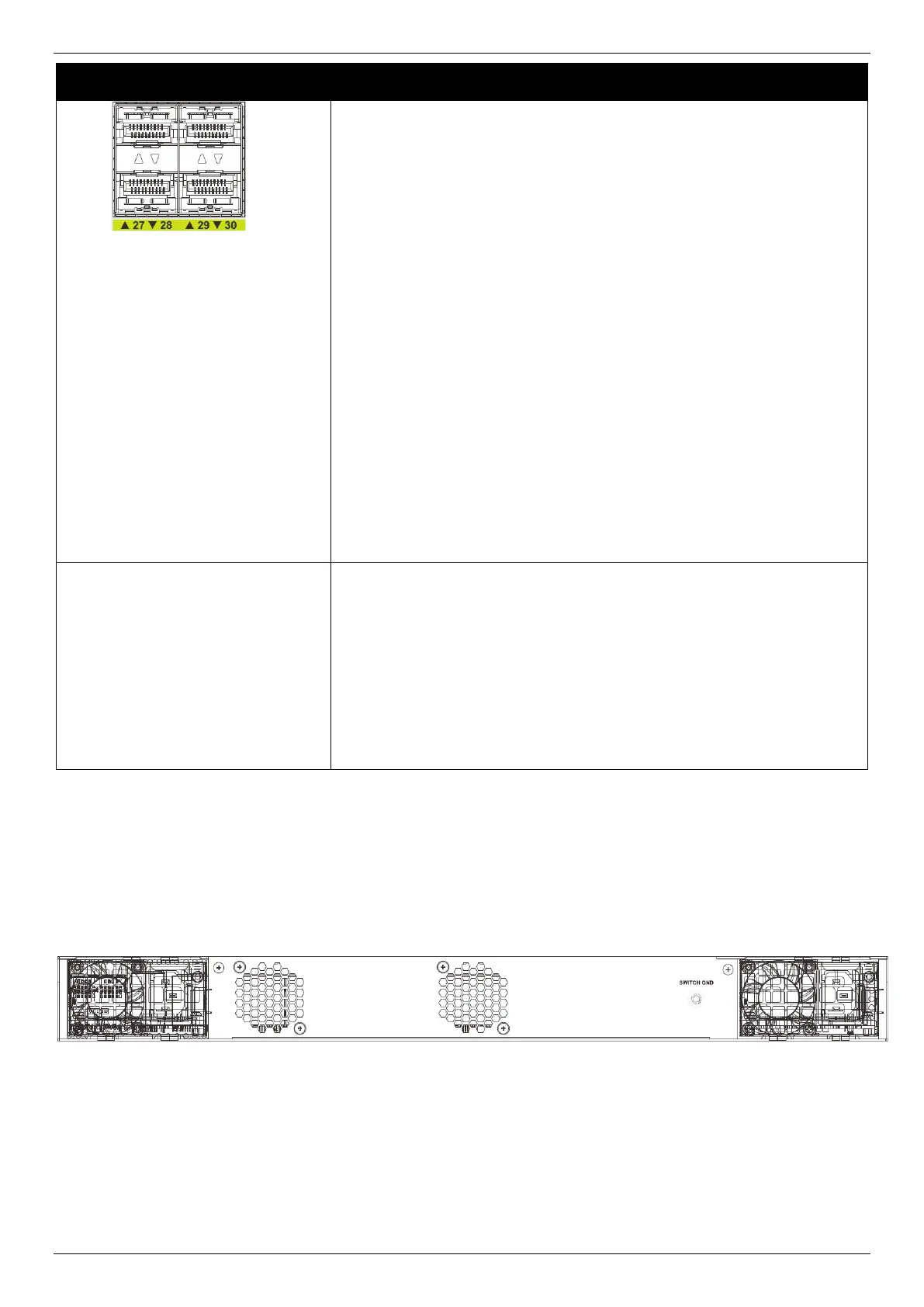
SFP28 Ports (N0. 27~30): The triangle LED indicates the Link/Act/Speed
status of 25G SFP28 ports. This LED will light solid green when there is a
connection (or link) to a 25 Gbps Ethernet device or solid amber when
there is a connection (or link) to a 10 Gbps Ethernet device on any of the
SFP28 ports. The LED will blink green when a 25 Gbps port is active or
blink amber when a 10 Gbps port is active. The LED will be off when there
is no link or activity.
Stack ID
This 7-segment LED can display numbers from 1 to 9 and the following
letters H, h, E, and G. The stacking ID (1 to 9) can be assigned manually by
the user or automatically by the system.
The letter ‘H’ will be displayed if this switch is the master switch in the
stack.
The letter ‘h’ will be displayed if this switch is the backup master switch in
the stack.
The letter ‘E’ will be displayed if there was an error in the system’s self-test.
The letter ‘G’ will be displayed when the Safeguard engine entered the
exhausted mode.
Please refer to the “LED Indicators” section in the Appendix A - Technical Specifications for more LED information.
Rear Panel Components
The rear panel of this switch features a GND and two hot-pluggable power supplies.
Figure 2-7 Rear panel view of the DMS-3130-30PS
Bekijk gratis de handleiding van D-Link DPS-PWR740AC, stel vragen en lees de antwoorden op veelvoorkomende problemen, of gebruik onze assistent om sneller informatie in de handleiding te vinden of uitleg te krijgen over specifieke functies.
Productinformatie
| Merk | D-Link |
| Model | DPS-PWR740AC |
| Categorie | Niet gecategoriseerd |
| Taal | Nederlands |
| Grootte | 10019 MB |


