Curtis Electronic Code Switch handleiding
Handleiding
Je bekijkt pagina 16 van 73
4 — INSTALLATION AND WIRING
Curtis Electronic Code Switch Module (ECS) – June 2022 Return to TOC
pg. 10
I/O PINS
e following table describes the I/O pins.
Table 3 ECS Pins
Pin Signal Name Description
J1-1 CAN Term
CAN terminating 120Ω resistor.
Note: To enable the resistor, connect this pin to pin J1-6.
J1-2 Interlock Input Active high; 12–96V
J1-3 Relay COM Power to relay; 12– 96V
J1-4 Relay NO Relay output
J1-5 CAN Low
J1-6 CAN High
J1-7 B+ Battery Positive
J1-8 B– Battery Common
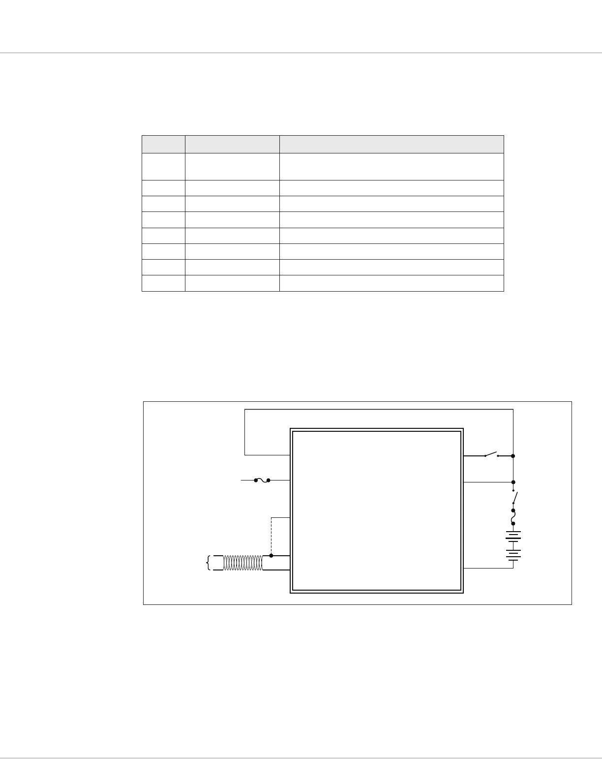
WIRING DIAGRAM
The following diagram illustrates a configuration in which the ECS is connected to an
interlock switch.
Figure 2
Wiring Diagram
Note: Use fuses that are appropriately sized for your application.
CAN HIGH
CAN LOW
CAN TERM
CONNECT J1-1 TO J1-6 FOR
120Ω CAN BUS TERMINATION
RELAY COM INTERLOCK INPUT
B+
B–
FUSE
CAN
PORT
BATTERY
(12-96V)
KEYSWITCH
J1-8
J1-7
J1-1
J1-6
J1-5
J1-3
RELAY N.O.
J1-4
J1-2
CONNECTED TO LOAD
FUSE
1 2 3
4 5 6
7
8 9
0C
Bekijk gratis de handleiding van Curtis Electronic Code Switch, stel vragen en lees de antwoorden op veelvoorkomende problemen, of gebruik onze assistent om sneller informatie in de handleiding te vinden of uitleg te krijgen over specifieke functies.
Productinformatie
| Merk | Curtis |
| Model | Electronic Code Switch |
| Categorie | Niet gecategoriseerd |
| Taal | Nederlands |
| Grootte | 8988 MB |


