Curtis 3401T handleiding
Handleiding
Je bekijkt pagina 33 van 62
3 — INSTALLATION AND WIRING
pg. 27
Return to TOC Curtis Model 3401T – August 2022
BATTERY CONNECTIONS
Connect the battery to the B+ and B– inputs (pins 16 and 15). Curtis recommends that you
include a fuse in the circuit that connects the battery to the B+ input as shown in Figure 3-2.
The fuse will protect the power system from external shorts and should be sized according to
your application’s requirements.
KEYSWITCH
e keyswitch input (pin 7) is active high. Connect the keyswitch input to B+ via a keyswitch.
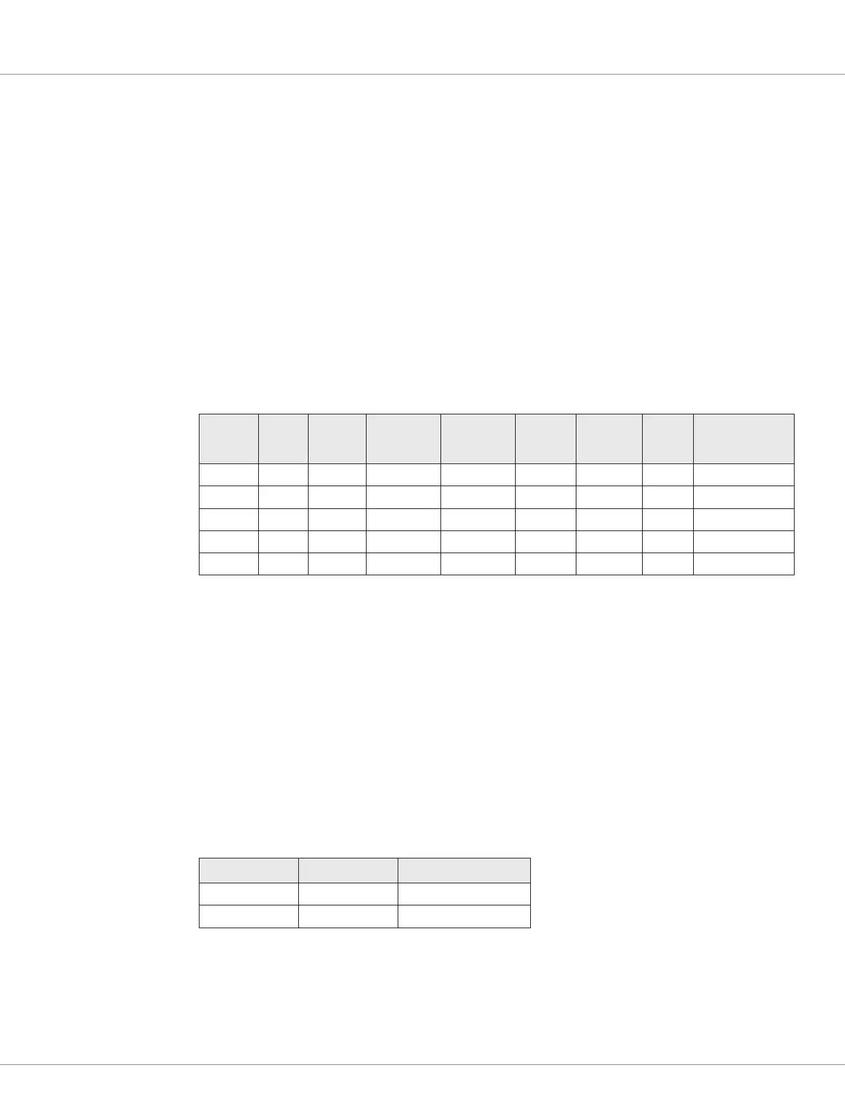
SWITCH 1–5 INPUTS
e switch 1–5 inputs can be congured for various functions. e following table lists the inputs’
pins, functions, and the parameters used to congure the functions:
Switch
Input
Pin Switch
Traction
Fault Code
Hydraulic
Fault Code
Analog Frequency Driver Parameter
1 5 x x x Sender 1 Type
2 13 x x x Sender 2 Type
3 6 x x x Sender 3 Type
4 14 x x x Sender 4 Type
5 8 x x Output Mode
Note: e frequency functions are reserved.
e following sections describe these inputs.
Switch Inputs
e switch 1–4 inputs can be congured as active high (switched to B+) or active low (switched to
B–). If pin 8 is congured as switch input 5, the input is active high. e switches’ statuses can be
used to turn signal icons on or o.
To congure pin 8 as a switch input, set the Output Mode parameter to Switch Input Mode.
e voltage range of the switch inputs is identical to the B+ operating voltage range. e input signals
must be within the range of threshold voltages listed in the following table:
Threshold Minimum Maximum
Active high 4.0V Maximum B+ voltage
Active low N/A 1.0V
Bekijk gratis de handleiding van Curtis 3401T, stel vragen en lees de antwoorden op veelvoorkomende problemen, of gebruik onze assistent om sneller informatie in de handleiding te vinden of uitleg te krijgen over specifieke functies.
Productinformatie
| Merk | Curtis |
| Model | 3401T |
| Categorie | Niet gecategoriseerd |
| Taal | Nederlands |
| Grootte | 7303 MB |


