Curtis 1356 handleiding
Handleiding
Je bekijkt pagina 18 van 58
14
Curtis 1356/1356P CAN Expansion Module Manual, Rev. A
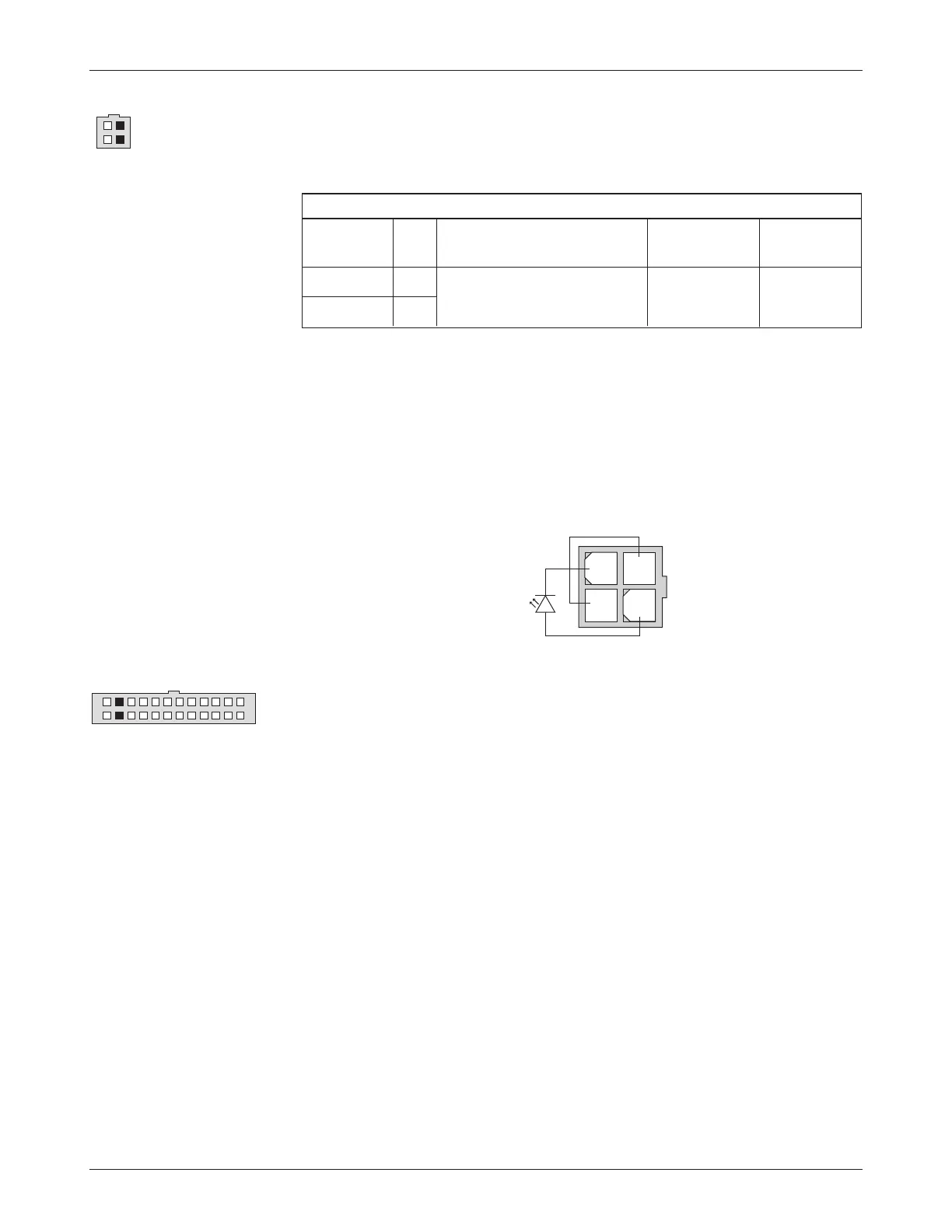
Serial Port
e Curtis 1313/1314 programmer or the Curtis Model 840 can be connected
to the 1356 /1356P’s serial port, J2.
Power is provided through J2-4 (+12V) and J2-2 provides the I/O ground
reference.
When the 840 is connected to the serial port, it will alternately show
BDI, hour meter, and fault information.
e serial port can also be used as an external Status LED fault code display.
When the serial port is used for fault code display, a jumper must be added
between J2-1 and J2-4, and an LED is connected between J2-2 and J2-3.
SERIAL PORT SPECIFICATIONS
protected
supported voltage
signal name pin protocol / devices data rate range
TX J2-3
1313 Handheld Programmer,
As required,
RX J2-1
1314 PC Programming Station,
9.6 to 56 kbit/s
-0.3 V to 12 V
Curtis 840 Display
CAN Bus Interface
e CAN bus interface will comply with CAN2.0B, active from 50 kbit/s to
1Mbit/s communication rate.
e 1356 /1356P will be terminated by an internal 1 kΩ resistor across
the CAN High and Low communication pins. is assumes a mid-truck con-
nection (not end-of-line).
If a 1356 /1356P without terminal resistance (models ending in -4101
or -6101) is at the end of the CAN bus, the bus needs to be terminated by
externally wiring a 120 Ω, ½ W resistor across CAN High and CAN Low.
2 — INSTALLATION & WIRING: I/O Signal Specifications
1
13
12
24
1
3
2
4
1
2
3
4
Bekijk gratis de handleiding van Curtis 1356, stel vragen en lees de antwoorden op veelvoorkomende problemen, of gebruik onze assistent om sneller informatie in de handleiding te vinden of uitleg te krijgen over specifieke functies.
Productinformatie
| Merk | Curtis |
| Model | 1356 |
| Categorie | Niet gecategoriseerd |
| Taal | Nederlands |
| Grootte | 7745 MB |


