Curtis 1353 handleiding
Handleiding
Je bekijkt pagina 12 van 55
2 — INSTALLATION AND WIRING
Curtis 1353 CANopen Expansion Module Manual – June 2021
Return to TOC
pg. 8
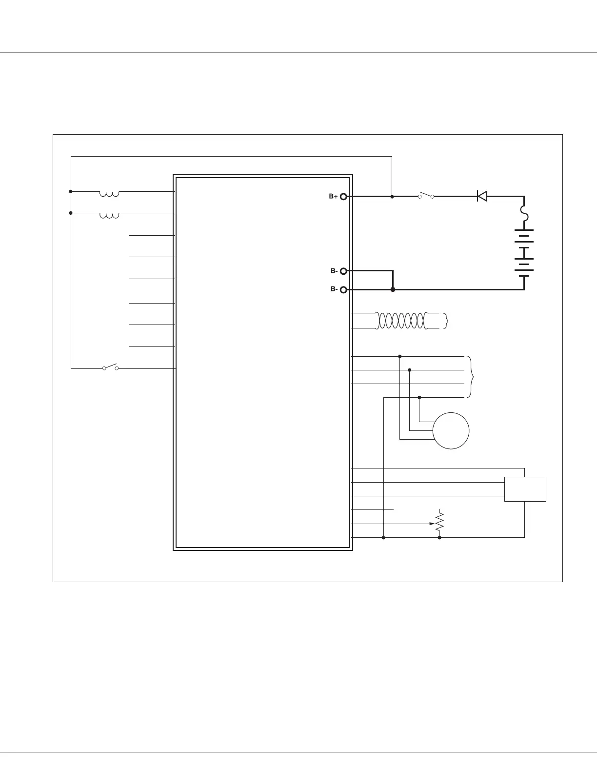
WIRING: BASIC CONFIGURATION
A basic wiring diagram is shown in Figure 3, and described below. e diagram shows the standard
power and battery connections, as well as some basic uses for the inputs and outputs.
J1-7
J1-8
J1-2
J1-9
J1-1
J1-23
J1-22
J1-21
J1-20
J1-19
J1-18
J1-17
J1-16
J1-15
J1-3
KEYSWITCH
SWITCH
BATTERY
(12–80V)
REVERSE
POLARITY
PROTECTION
PROPORTIONAL
VALVE
CONTACTOR
CAN PORT
1353
ANALOG INPUT 1/ENCODER 1A
ANALOG INPUT 2/ENCODER 1B
ANALOG INPUT 3/ENCODER 2A
ANALOG INPUT 4/ENCODER 2B
I/O GND
INPUT/OUTPUT 1
INPUT/OUTPUT 2
INPUT/OUTPUT 3
INPUT/OUTPUT 4
INPUT/OUTPUT 5
INPUT/OUTPUT 6
INPUT/OUTPUT 7
INPUT/OUTPUT 8
INPUT/OUTPUT 9
CAN H
CAN L
+5V
ENCODER
J1-14
J1-13
J1-6
J1-5
J1-4
0–15V IN
RESISTIVE THROTTLE,
RTD, etc.
J1-10
J1-11
J1-12
SERIAL PORT
(4-pin Molex)
4
3
1
2
DISPLAY
8
6
5
+12V
ANALOG INPUT 6/RX
ANALOG INPUT 5/TX
Figure 3
Basic wiring diagram, Curtis 1353 CANopen expansion module.
Power Connection
e battery is connected to the module’s B+ pin though a fuse, a diode, and a keyswitch. e fuse
protects the wiring in the event of a short or failure. e return path of the coils is also brought back
to the B+ pin to utilize the yback diodes connected inside the 1353 between B+ and each driver
output.
e keyswitch is used to turn on the system. When the keyswitch is closed, B+ goes high and the
1353’s power supply brings up the module.
Bekijk gratis de handleiding van Curtis 1353, stel vragen en lees de antwoorden op veelvoorkomende problemen, of gebruik onze assistent om sneller informatie in de handleiding te vinden of uitleg te krijgen over specifieke functies.
Productinformatie
| Merk | Curtis |
| Model | 1353 |
| Categorie | Niet gecategoriseerd |
| Taal | Nederlands |
| Grootte | 6945 MB |


