Crestron Green Light GL-EXP-DIMU-DALI handleiding
Handleiding
Je bekijkt pagina 2 van 2
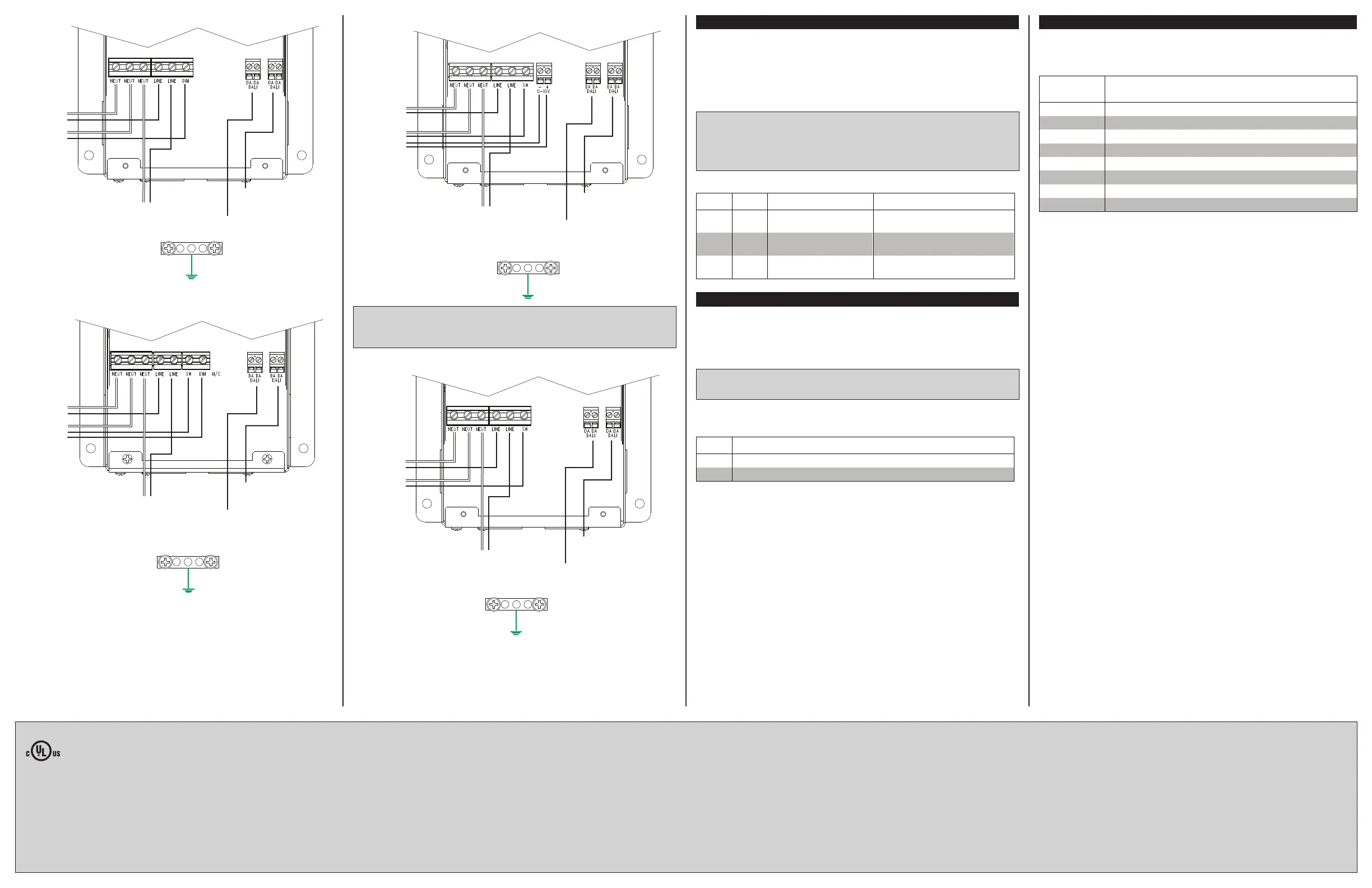
Wire the GL-EXP-DIMU-DALI
Wire the GL-EXP-DIMFLV-DALI
Wire the GL-EXP-SW-DALI
Wire the GL-EXP-DIMFDB-DALI
Dimming Mode
(GL-EXP-DIMU-DALI Only)
The GL-EXP-DIMU-DALI is capable of automatically detecting the attached load type and
setting itself for Forward Phase (leading edge) or Reverse Phase (trailing edge) dimming
mode accordingly. In addition, the unit can be forced to perform forward or reverse phase
dimming by overriding the automatic detection.
Disabling the Autodetect mode should not be necessary and is not recommended unless
suggested by a Crestron technical support representative.
WARNING: RISK OF SERIOUS PERSONAL INJURY. Turn off power at the circuit
breaker(s) prior to changing any switch settings. Changing settings with the power on can
result in serious personal injury and damage to the device.
WARNING: Incorrectly setting these switches to force the wrong mode can cause
damage to the dimmer and lighting xture.
The dimming mode can be changed by adjusting the SW3 and SW4 DIP switches as
detailed below.
Zero-Cross Mode
(GL-EXP-DIM-DALI, GL-EXP-DIMU-DALI, and GL-EXP-DIMFDB-DALI Only)
The GL-EXP-DIM-DALI, GL-EXP-DIMU-DALI, and GL-EXP-DIMFDB-DALI ship with SW1 set
to OFF. The devices should generally be left in this state. To deal with certain unusual line
conditions, Crestron Technical Support may recommend setting this switch to ON for
Filtered Zero-Cross mode.
WARNING: RISK OF SERIOUS PERSONAL INJURY. Turn off power at the circuit
breaker(s) prior to changing any switch settings. Changing settings with the power on can
result in serious personal injury and damage to the device.
The zero-cross mode is set using the SW1 DIP switch. Refer to the following table when
setting the zero-cross detection mode.
Switch Settings for the SW1 DIP Switch
SW1 DESCRIPTION
Off Simple zero-cross mode.
On Filtered zero-cross mode.
Error States
The ERR LED blinks a specic pattern to indicate an error. The blink patterns are
described in the table below as, for example, 1-1 or 2-1. A 1-2 blink pattern means that
the LED blinks one time, pauses for one second, blinks two times, pauses for ve
seconds, and then repeats until the error is corrected.
LED BLINK
PATTERN
ERROR STATE
1-1 The slave processor is in bootloader.
1-2 The slave processor is unresponsive.
1-3 The slave processor rmware update failed.
2-1 There is an over current error.
2-2 A FET is shorted.
2-3 An over temperature error exists.
2-4 An over-voltage error exists.
3-1 A zero-cross sync error exists.
This product is Listed to applicable UL Standards and requirements by Underwriters Laboratories Inc.
Federal Communications Commission (FCC) Compliance Statement
This device complies with part 15 of the FCC Rules. Operation is subject to the following two
conditions: (1) This device may not cause harmful interference, and (2) this device must accept any
interference received, including interference that may cause undesired operation.
CAUTION: Changes or modications not expressly approved by the manufacturer responsible for
compliance could void the user’s authority to operate the equipment.
NOTE: This equipment has been tested and found to comply with the limits for a Class A digital
device, pursuant to part 15 of the FCC Rules. These limits are designed to provide reasonable
protection against harmful interference when the equipment is operated in a commercial environment.
This equipment generates, uses, and can radiate radio frequency energy and, if not installed and used
in accordance with the instruction manual, may cause harmful interference to radio communications.
Crestron Electronics, Inc. Installation & Operation Guide - DOC. 7584A
15 Volvo Drive Rockleigh, NJ 07647 (2043188)
Tel: 888.CRESTRON 06.15
Fax: 201.767.7576 Specications subject to
www.crestron.com change without notice.
Operation of this equipment in a residential area is likely to cause harmful interference in which case the
user will be required to correct the interference at his own expense.
Industry Canada (IC) Compliance Statement
CAN ICES-3(A)/NMB-3(A)
The product warranty can be found at www.crestron.com/warranty.
The specic patents that cover Crestron products are listed at patents.crestron.com.
Crestron, the Crestron logo, Crestron Green Light, and Crestron Toolbox are either trademarks or
registered trademarks of Crestron Electronics, Inc. in the United States and/or other countries. DALI
is either a trademark or registered trademark of ZVEI - Zentralverband Elektrotechnik- und
Elektronikindustrie in the United States and/or other countries. UL and the UL logo are either
trademarks or registered trademarks of Underwriters Laboratories, Inc. in the United States and/or
other countries. Other trademarks, registered trademarks, and trade names may be used in this
document to refer to either the entities claiming the marks and names or their products. Crestron
disclaims any proprietary interest in the marks and names of others. Crestron is not responsible for
errors in typography or photography.
This document was written by the Technical Publications department at Crestron.
©2015 Crestron Electronics, Inc.
Pass Through to
Additional
Module
From Circuit
Breaker
To Dimmed
Load
From DALI
Network
To Additional
DALI Modules
Pass Through to
Additional
Module
From Circuit
Breaker
To Dimmed
Load
From DALI
Network
To Additional
DALI Modules
Pass Through to
Additional
Module
From Circuit
Breaker
To Dimmed
Load
From DALI
Network
To Additional
DALI Modules
Pass Through to
Additional
Module
From Circuit
Breaker
To Switched
Load
From DALI
Network
To Additional
DALI Modules
3. Replace the cover and cover screws.
4. Apply power to the module. The power indicator LED lights indicating that power is
supplied to the module.
NOTE: When wiring the GL-EXP-DIMFLV-DALI, the 0-10V control wires from the + and –
terminals can be wired as Class 1 or Class 2. The unit ships with a barrier to the right of
the 0-10V terminal block for Class 1 wiring. If using Class 2 wiring, move this barrier to the
left of the 0-10V terminal block.
SW3 SW4 DIMMING MODE LOAD TYPES
Off Off Autodetect (Default,
recommended)
All
On Off Forward Phase Magnetic low voltage, NCC, 2-wire
dimmable uorescent
Off On Reverse Phase Incandescent, Electronic Low
Voltage
Bekijk gratis de handleiding van Crestron Green Light GL-EXP-DIMU-DALI, stel vragen en lees de antwoorden op veelvoorkomende problemen, of gebruik onze assistent om sneller informatie in de handleiding te vinden of uitleg te krijgen over specifieke functies.
Productinformatie
| Merk | Crestron |
| Model | Green Light GL-EXP-DIMU-DALI |
| Categorie | Niet gecategoriseerd |
| Taal | Nederlands |
| Grootte | 657 MB |


