Crestron CLTIBN-4HSW4 handleiding
Handleiding
Je bekijkt pagina 2 van 12
Terminal Block with Breaker Crestron CLTIBN
Terminal Block & Module Locations (Double-wide Enclosure)
GROUNDING STRIP
TERMINAL BLOCKS
WIRING MODULES
NOTE: Unless otherwise indicated, the lighting system
specified in this guide is modular, requiring assembly in
the field by a licensed electrician, in accordance with all
national and local codes.
Terminal Block Installation and
Field Wiring
CAUTION: RISK OF ELECTRIC SHOCK—MORE
THAN ONE DISCONNECT SWITCH MAY BE
REQUIRED TO DE-ENERGIZE THE EQUIPMENT
BEFORE SERVICING.
NOTE: Both left-side and right-side adhesive wiring
labels are provided. The left-side labels are used in both
single and double-wide enclosures. The right-side labels
are only used in double-wide enclosures.
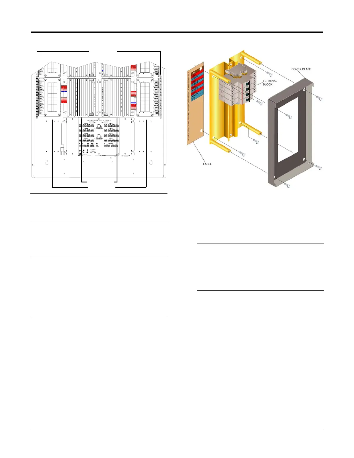
Using the diagram in the next column as reference, install
the terminal block in the CAENIB enclosure.
1. Using a Phillips screwdriver, remove the four
screws securing the cover plate to the CLTIBN
and remove the cover plate.
2. Remove the backing from the left or right
adhesive wiring label. Place the label in the
location where the CLTNIB is to be mounted on
the CAENIB. Align the holes in the label with
the appropriate holes in the CAENIB. Refer to
the latest version of the CAENIB Installation
Guide for information on mounting locations.
CLTIBN Exploded View (CLTIBN-1DELV4 Shown)
3. Use the four supplied self-tapping pan Phillips
screws (8B x ¼-inch (6 mm) length) to secure
the terminal block and the appropriate (left or
right) wiring label to the Crestron Automation
Enclosure. The wiring label lies beneath the
terminal block as shown in the terminal block-to-
module wiring diagrams on page
4.
NOTE: When installed with other terminal blocks,
CLTI-4IND and CLTI-2IND terminal blocks should
be installed at the top of a CAENIB enclosure and
grouped with other CLTI-4IND and CLTI-2IND
terminal blocks.
NOTE: Use copper conductors only – rated 75°C.
4. With the branch circuit breakers and the terminal
block circuit breakers turned off, connect the
circuit feed (LINE and NEUTRAL) and
controlled circuit (LOAD) wires to the terminal
block per the markings provided on the wiring
label (as shown in the terminal block-to-module
wiring diagrams on page
4). Terminal blocks
accept one 2.5 - 6.0 mm
2
wire. Circuit breaker
lugs accept one conductor up to 16 mm
2
. Wires
should be stripped to 12 mm. Tighten terminal
blocks to 1 Nm. Tighten circuit breaker lugs to
1.2 Nm.
5. Grounding terminal blocks are available in the
cabinet for termination of ground wires. Tighten
to 4 Nm (2.5 - 6.0 mm
2
), 4.5 Nm (10.0 mm
2
), or
5.1 Nm (16 - 25 mm
2
).
2 • Terminal Block: CLTIBN Installation Guide – DOC. 6561A
Bekijk gratis de handleiding van Crestron CLTIBN-4HSW4, stel vragen en lees de antwoorden op veelvoorkomende problemen, of gebruik onze assistent om sneller informatie in de handleiding te vinden of uitleg te krijgen over specifieke functies.
Productinformatie
| Merk | Crestron |
| Model | CLTIBN-4HSW4 |
| Categorie | Niet gecategoriseerd |
| Taal | Nederlands |
| Grootte | 2218 MB |


