Continental 1RE-N-HD handleiding
Handleiding
Je bekijkt pagina 10 van 44
10
REACH-INS & ROLL-INS
OPERATIONS MANUAL
REMOVAL AND REPLACEMENT
OF HINGE MECHANISM
Before attempting any work on your refrigerator or freezer, it is
strongly recommended that all contents be removed and stored
in a walk-in or other refrigerated space. Disconnect power by
unplugging the cabinet, or switching off circuit breaker. The
following tools are needed to remove the hinge: straight-blade
screwdriver and philips screwdriver with large (#3) tip.
To remove a hinge, open the door approximately 90° and lift
it off the hinge bodies. Remove the hinge pin and adjustment
plate from the door (see Figure 8A) by loosening the adjustment
screws. Remove the hinge body from the face of the cabinet by
loosening the (3) flat-head machine screws. To remove the lock
keeper from the cabinet, remove the 2 screws on the inside edge
of the keeper (see Figure 8A) and slide it off the base. If the
white, nylon cam needs to be removed from the hinge body, a
straight blade screwdriver may be used to carefully pry the cam
out of the body. Be careful not to damage the cam, as the nylon
material is soft. Reverse the cam by rotating it 180° and pressing
it firmly back in place.
RE-HINGING DOORS (Reach-Ins)
Single section, solid long door models are rehingeable in the
field, without the need to modify the cabinet. A scraper or
flat-blade screwdriver, a philips screwdriver and wire crimpers
will be needed. Before attempting to rehinge your unit, unload
all contents and store in walk-in or other refrigerated space.
Disconnect power to the cabinet.
Open the door approximately 90° and lift it off the hinges.
Remove the hinge pin assemblies from the door (see Figure
8A). Reverse each pin by rotating it 180° and reattaching it to the
door. Remove the hinge bodies and lock keeper(s) from the front
of the cabinet. Remove the white, nylon cam from the hinge
body. (A straight blade screwdriver may be used to carefully
pry the cam out of the body, without damaging it.) Reverse the
cam by rotating it 180° and pressing it firmly back in. Remove
the light switch from the front of the cabinet and pull the switch
out of the hole.
Remove the screws and plug button from the face of the cabi-
net, on the opposite side hinge locations. The wires for the light
switch will be coiled up in the insulation, behind the plug button.
Carefully pull the wires out and install female connectors for the
light switch. Remove the old light switch from behind the top
hinge and remove the wire connectors.
DOOR REMOVAL AND ADJUSTMENT
During installation, it may become necessary to remove the
cabinet doors to facilitate passage through narrow doorways or
hallways. To remove a door, carefully pry off all hinge covers
using a sharp tool or knife (see Figure 8). Swing the door to
the open-door position (90°) and carefully lift the door upward,
so the hinge pin (attached to the door) clears the hinge body
(mounted to the cabinet). If it is necessary to remove the hinge
bodies from the cabinet face, use caution when loosening the
top hinge bodies, as they cover the light switch plunger. To rein-
stall the door, reverse the above procedure. (For glass doors,
see “Optional Accessories”).
All doors are aligned at the factory, however vibration during
transit may cause doors to shift and adjustment may be neces-
sary. If the door(s) require realignment, carefully pry off all hinge
covers (see Figure 8A) using a sharp putty knife or flat-blade
screwdriver. Loosen the screws securing the hinge bodies to the
face of the cabinet and slide the door into alignment. Hold the
door firmly in place and tighten all screws securely.
If the door gasket(s) do not seal properly to the cabinet face
and there are gaps between the gasket and the face on the hinge
edge, adjust the door by removing the hinge covers (see Figure
8A) and loosening the adjustment screws securing the hinge pin
to the door. Push the face of the door towards the face of the
cabinet, so the gasket firmly contacts the cabinet. If the door is
pressed too tight against the cabinet, the gasket will pinch along
the hinge side and the door will not close and seal properly. Hold
the door firmly in place and tighten all screws securely. Open
and close the door several times to check that the gasket seals
properly all the way around the door. Re-adjust if necessary and
make sure all screws are tight. Replace all hinge covers.
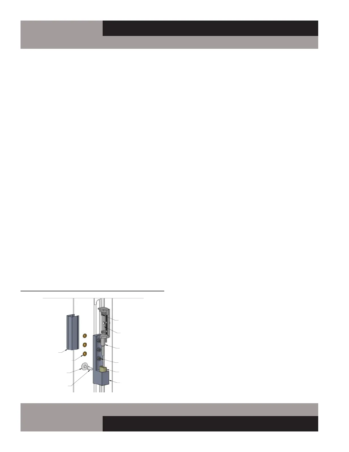
FIGURE 8A: Reach-In/Roll-In Hinge Adjustment
C
DETAIL C
SCALE 1 : 1.5
HINGE
COVER
HINGE
BODY
ADJUSTMENT
PLATE
REVERSIBLE
CAM
HINGE
PIN
ADJUSTMENT
SCREWS
LIGHT SWITCH
THREADED HOLE
SCREWS
FRONT OF
LH DOOR
SWITCH
ACTUATOR
HINGE ADJUSTMENT
REACH-IN/ROLL-IN
(TOP HINGE ONLY)
(IN CABINET FACE)
(LEFT-HAND DOOR, TOP HINGE SHOWN)
Bekijk gratis de handleiding van Continental 1RE-N-HD, stel vragen en lees de antwoorden op veelvoorkomende problemen, of gebruik onze assistent om sneller informatie in de handleiding te vinden of uitleg te krijgen over specifieke functies.
Productinformatie
| Merk | Continental |
| Model | 1RE-N-HD |
| Categorie | Koelkast |
| Taal | Nederlands |
| Grootte | 9584 MB |


