Cleco DGD 946823D7 handleiding
Handleiding
Je bekijkt pagina 29 van 54
29
P1713E-EN
2013-12
EN
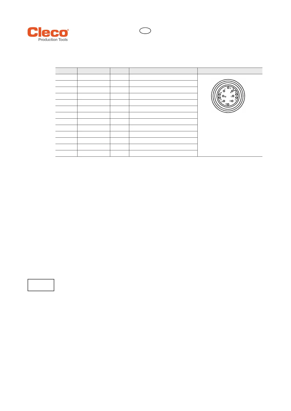
6.3 Pin-Out
6.4 Description Torque / Angle Measuring System
• The transducer is equipped with a telemetry system and therefore it has no slip rings.
• The transducers can be installed as components in built-in nutsetters and optionally in offset attach-
ments and angle attachments.
• The transducer is to be viewed as a complete unit. The transducer assembly (measuring shaft, antenna
system, rotor electronics and stator electronics) is a unified assembly whose components may not be
replaced individually.
The rotor electronics assembly is mounted on the measuring shaft. It is connected to the strain gage bridge
and the rotor antenna system.
Die stator electronics assembly is located in the transducer housing. It contains the evaluation circuit, the
stator antenna system and the 12-pin system connector.
Torque and angle are measured directly in the nutsetter attachment, that is, in the parts conducting the
force to the fastener. The angle is measured with the drive wheel in the angle head attachment.
Only measuring devices which are galvanically separated from the protective earth conductor are permissi-
ble for measuring the torque / angle encoder signals directly on the transducer (e. g. oscilloscope with isola-
tion transformer). When measuring, ensure that both 0 V reference connections of the transducer (0 V-
torque/Pin D and 0 V-supply/Pin E) cannot be short-circuited.
Angle measurement
The integrated incremental angle encoder traces the angle with two angle tracks. The phase shift between
these depends on the sense of rotation. The angle signals are read by query of the 360 magnetic poles of
the pole wheel and are then transferred to the measuring electronics at amplified voltage/voltage increase
of 12 V.
Torque measurement and calibration
Transducer with torque measurement on the shaft.
Torque measurement is made symmetrically for right and left-rotating torques (tightening and loosening
direction).
The torque is measured by a full-bridge strain-gage circuit installed on the rotating output shaft in realtime
and is then telemetrically transferred to the stator electronics.
Pin Cable colour Signal Description
A- -nc
12 pin round connector
Lumberg SGR 120,
Binder Series 680
no. 09-0331-90-12
with screw cap according to DIN 45
321
B Brown ANGA Angle output A
C Green TQ Torque output
D Yellow 0 VA 0 V torque reference connection
E Gray 0 V 0 V supply
F Pink +12 V Supply
G Blue ANGB Angle output B
H Red RxD+ Interface
J Black RxD- Interface
K Violet CAL Calibration signal
L Gray / pink TxD- Interface
M Red / blue TxD+ Interface
Housing PE Shield connection
If this is not observed failures or measuring error by potential equalization currents (between PE, 0 V TQ
and 0 V supply) in the torque measuring circuit may result.
ATTENTION
!
Bekijk gratis de handleiding van Cleco DGD 946823D7, stel vragen en lees de antwoorden op veelvoorkomende problemen, of gebruik onze assistent om sneller informatie in de handleiding te vinden of uitleg te krijgen over specifieke functies.
Productinformatie
| Merk | Cleco |
| Model | DGD 946823D7 |
| Categorie | Niet gecategoriseerd |
| Taal | Nederlands |
| Grootte | 5397 MB |


