Cigweld Transmig 4RT handleiding
Handleiding
Je bekijkt pagina 19 van 62
INSTALLATION/SETUP TRANSMIG 4RT
Manual 0-5245 3-3 INSTALLATION/SETUP
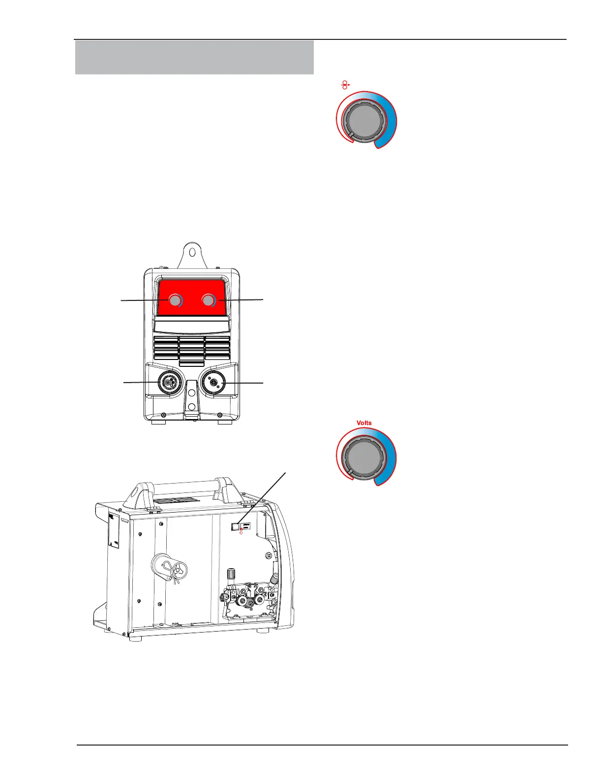
3.06 4RT Wire Feeder Controls,
Indicators and Features
The 4RT Wirefeeder is designed to be used with the
Transmig 350i, 450i, 550i. Select MIG Process and
Remote 10 pin indicator on the Transmig 350i, 450i,
550i Power Source to enable the controls on the 4RT
wirefeeder. See the Transmig 350i, 450i, 550i Operating
manual for details.
The 4RT Wirefeeder is also designed to be used with
the Transmig 250i. Select MIG Process and REMT in the
Advanced Features menu on the Transmig 250i Power
Source to enable the controls on the 4RT wirefeeder. See
the Transmig 250i Operating manual for details
Volts
Wirespeed
Left Knob
Right Knob
1
2
3
4
Art # A-10404
Figure 3-1: 4RT Front Panel Controls
Art # A-11283
5
Figure 3-2: 4RT Local/Remote Switch
The Tweco MIG Torch will connect to the 4RT just as it
does to the power source. The electrode Polarity setting is
done at the power source. See sub sections 3.09 and 3.10.
1. Left Knob: WFS (Wire Feed Speed) Control
Amperage Control
Wirespeed
Left Knob
The Left Knob controls the Amperage and the Wirespeed
in the wirefeeder. It adjusts the preview wire speed dis-
play in the power source. The amperage control knob
adjusts the amount of welding current delivered by the
power source. In MIG mode, the amperage knob adjusts
the speed of the wire feed motor (which in turn adjusts
the output current by varying the amount of MIG wire
delivered to the welding arc). The optimum wire speed
required is dependent on the type of welding application.
The setup chart on the inside of the wire feed compart-
ment door of the Transmig 250i provides a brief summary
of the required output settings for a basic range of MIG
welding applications. The value may also be adjusted while
a weld is in progress – if this occurs, the left display will
briefly switch to show the adjusted value as the knob on
the 4RT is turned, and will automatically revert back to
showing the set weld current measurements when the
knob is not being turned.
2. Right Knob: MIG Voltage Control
Right Knob
MIG Voltage Control
The Right knob is used to adjust the output voltage of
the power source. It adjusts the preview voltage display
in the power source. The welding voltage is increased
by turning the knob on the 4RT clockwise or decreased
by turning the knob anti-clockwise. The optimum volt-
age level required is dependent on the type of welding
application. The setup chart on the inside of the wire
feed compartment door of the Transmig 250i provides a
brief summary of the required output settings for a basic
range of MIG welding applications. The value may also
be adjusted while a weld is in progress – if this occurs,
the left display on the power supply will briefly switch to
show the adjusted value as the knob on the 4RT is turned,
and will automatically revert back to showing the set weld
current measurements when the knob is not being turned.
Bekijk gratis de handleiding van Cigweld Transmig 4RT, stel vragen en lees de antwoorden op veelvoorkomende problemen, of gebruik onze assistent om sneller informatie in de handleiding te vinden of uitleg te krijgen over specifieke functies.
Productinformatie
| Merk | Cigweld |
| Model | Transmig 4RT |
| Categorie | Niet gecategoriseerd |
| Taal | Nederlands |
| Grootte | 8070 MB |
