Carel Hecu handleiding
Handleiding
Je bekijkt pagina 9 van 60
9
Hecu +0300023EN rel. 1.2 - 14.12.2021
2.2 18-24 A three-phase inverter
Go to www.carel.com to check for any new versions of the technical documents.
The following documents are taken from technical leafl et +0500048IE rel. 2.2 of
07/11/2014.
C1
C2
L1/LL2/N L3UVW
1 2345678910
E
F
Fig. 2.b
Description of the terminals
Ref. Description
L1/L, L2/N, L3
Three-phase power input
earth conn. (*)
L1/L, L2/N
Single-phase power input
earth conn. (*)
U, V, W
Motor output
earth conn. (*)
C1, C2
Terminals for optional DC choke on PSD10184** and
PSD10244**
1.2 Relay output
30 V
RS485/ModBus® connection4 Tx/Rx+
5 Tx/Rx-
6 PTC input
7 24 Vdc
Auxiliary voltage
80V
9STOa
Safe torque off digital input (**)
10 STOb
E
PE
F (LED)
POWER (green) drive powered
RUN/FAULT (green/red) drive running / active alarm
DATA (yellow) communication active
(*) The earth connections in the controller are electrically connected together and to PE.
(**) For the drive to be enabled for operation, apply
24 Vac/Vdc to the safe torque off digital input. The polarity is indiff erent for direct
current power supply.
Main technical specifi cations
Reference technical docu-
ment
+0500048IE rel. 2.2 of 07/11/2014
Operating temperature -20T60 °C
Humidity < 95% RH non-condensing
Environmental pollution level Max 2
Input voltage 200 - 240V ± 10%, 50 - 60Hz, 1~
Output voltage 0 - Input voltage
Output frequency 0 - 500 Hz
Maximum length 5 m
Switching frequency 4, 6, 8 kHz
Protection functions
Drive: short circuit, overcurrent, earth fault, over-
voltage and undervoltage, overtemperature
Motor: overtemperature and overload (150% Inom
for 1 min)
System: Safe torque OFF input, no communication
Frequency resolution 0.1 Hz
Inputs
1 motor protection input: PTC temp. sensor or
voltage-free contact, maximum current 10 mA,
maximum length 25 m.
Outputs 1 relay: prog. output, voltage-free cont.: 240 Vac, 1 A
Serial input RS485, Modbus® protocol, max baud rate 19200 bit/s
24 Vdc aux. power supply Double insulation, 10% precision, 50 mA max
Maximum length 100 m shielded cable
Ingress protection IP20
CE conformity:
2006/95/EC EN 61800-5-1: Adjustable speed electrical power drive systems.
Safety requirements. Electrical, thermal and energy.
2004/108/EC EN 61800-3, ed. 2.0: Adjustable speed electrical power drive systems. EMC
requirements, including specifi c test methods.
EN61000-3-2: Electromagnetic compatibility (EMC) Part 3-2: Limits for har-
monic current emissions (equipment input current <= 16A per phase).
EN61000-3-12: Electromagnetic comp. (EMC) Part 3-12: Limits - Limits for
harmonic current emissions (equipment input current > 16A and <=75A
per phase).
Rated values
The following table shows the rated input current and output current values,
as well as the specifi cations for sizing the cables (cross-section, maximum
length) and the fuses. The values refer to an operating temperature of 60°C
and a switching frequency of 8 kHz, unless otherwise specifi ed.
Models PSD1018400 PSD1024400
Rated input current at 400V 23 A 30 A
Fuse or type B circuit breaker 32 A 40 A
Power cable size 4 mm
2
6 mm
2
Rated output current 18 A 24 A
Rated output power at 400V 10.5 kW 14 kW
Maximum total dissipation 320 W 485 W
Maximum dissipation on the heat sink 250 W 380 W
Min. motor cable size 4 mm
2
4 mm
2
Max. motor cable length 5 m 5 m
Tab. 2.b
DC choke
The DC choke is an option supplied separately to be used with the three-
phase Power+ drive for reducing harmonic current distortion to the
levels specifi ed by byEN61000-3-12.
C1
C2
L1/L L2/N L3 U V W
12 345 678910
F
PE
2m max
C1
C2
Fig. 2.c
• connect the DC choke to terminals C1 and C2;
• earth the DC choke using the metal terminal provided;
• to connect the DC choke, use a cable with the same cross-section as
the power cable;
• maximum cable length is 2 m.
DC choke P/N to be installed on Power+ drive Type
PSACH10200
PSD1024400, PSD10244A0,
PSD1018400, PSD10184A0
1.6 mH, 45 A peak
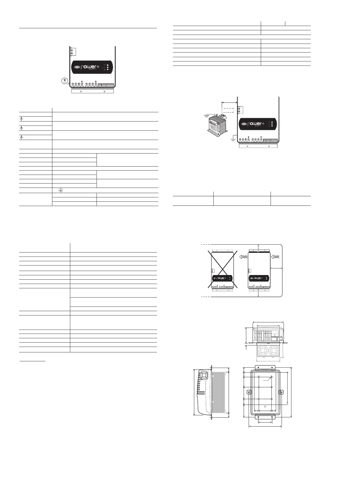
Cooling
All Power+ drives feature forced ventilation for cooling the heat sink.
Suffi cient air fl ow and air change must be provided inside the electrical
panel. All Power+ drives have the fan located on the right-hand side.
Avoid hot air intake to the fan.
C1
C2
L1/L L2/N L3 U V W
12 345 678910
C1
C2
L1/L L2/N L3 U V W
12 345 678910
≥ 200 mm
≥ 200 mm
≥ 100 mm
Fig. 2.d
Dimensions
26 2675
M5
127
131
86
82
2660
70,8
190
268
240
289,2
71,3
12
27,9
24,6
24,6
33,2
173
80
192,3
Fig. 2.e
Bekijk gratis de handleiding van Carel Hecu, stel vragen en lees de antwoorden op veelvoorkomende problemen, of gebruik onze assistent om sneller informatie in de handleiding te vinden of uitleg te krijgen over specifieke functies.
Productinformatie
| Merk | Carel |
| Model | Hecu |
| Categorie | Niet gecategoriseerd |
| Taal | Nederlands |
| Grootte | 10743 MB |


