Carel Hecu handleiding
Handleiding
Je bekijkt pagina 34 van 60
34
Hecu +0300023EN rel. 1.2 - 14.12.2021
In: Type of unit
This parameter assigns the function of Main or Secondary to the controller.
The Hecu sistema only allows MPXPRO Main units and therefore this
parameter must always be set to “1”.
Par. Description Def Min Max UOM
In Type of unit: 0 = Secondary; 1 = Main 0 0 1 -
Tab. 7.i
Sn: Number of Secondary units in the local network
This parameter tells the Main controller how many Secondary controllers
it needs to manage in the local network. The Hecu sistema only allows
MPXPRO Main units and therefore this parameter must always be set to
“0”.
Par. Description Def Min Max UOM
Sn Number of Secondary units in the local
network
0 = no Secondary unit
005-
Tab. 7.j
H0: Serial or Main/Secondary network address
Parameter H0 defi nes the MPXPRO controller serial addressed.
Par. Description Def Min Max UOM
H0 Serial or Main/Secondary network address 199 0 199 -
Tab. 7.k
The addresses must obey the following logic:
Device Address
MPXPRO 1 11
MPXPRO 2 12
MPXPRO 3 13
MPXPRO 4 14
MPXPRO 5 15
End of procedure
Press Prg/mute for 5 seconds to exit the guided commissioning
procedure.
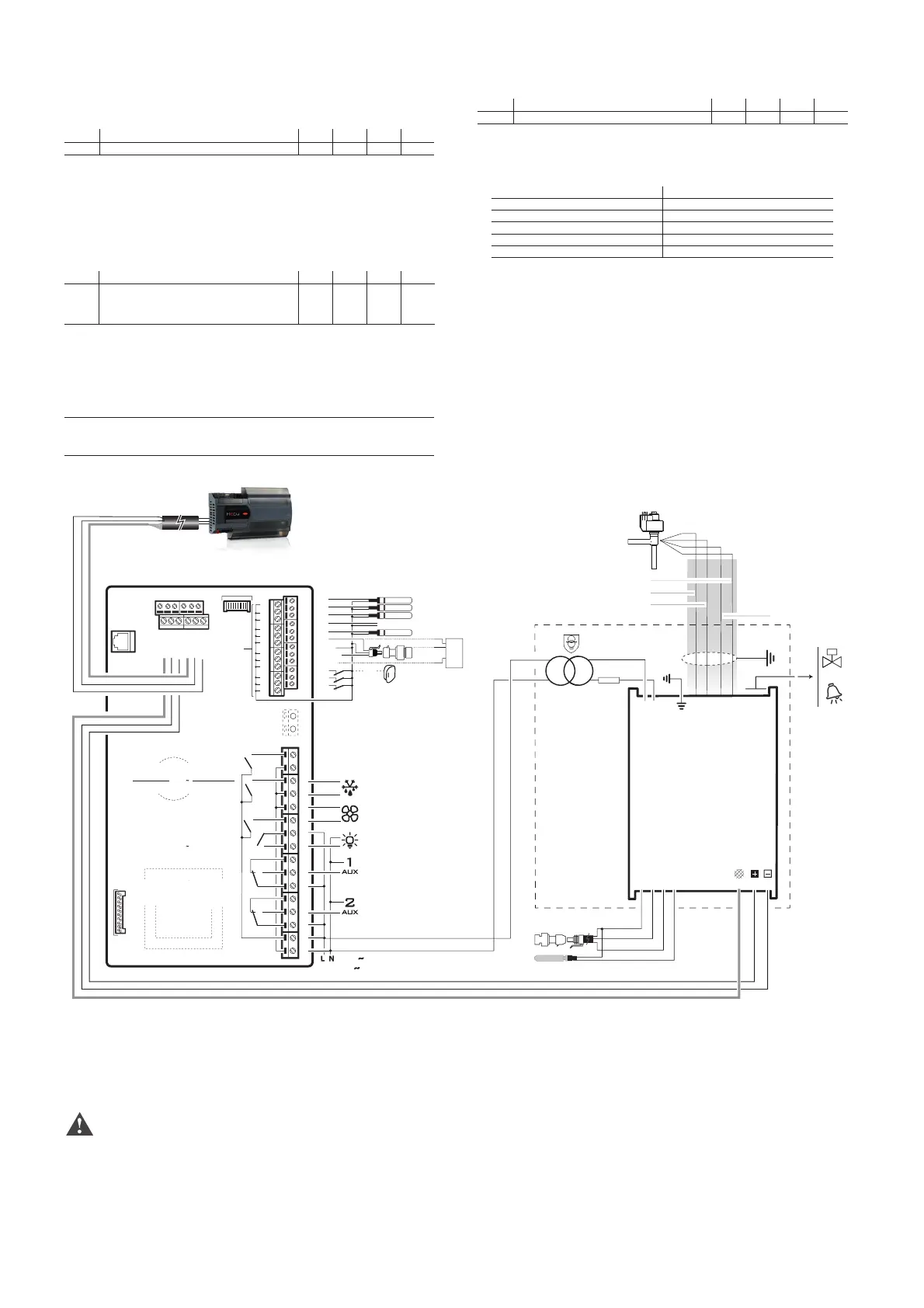
7.2 Ultracella confi guration (SW version ≥ 2.0)
General connection diagram
G
G0
VBAT
COMA
NOA
1
3
24
GND Tx/Rx
DI1
S4
S3
S2
S1
GND
DI2
VREF
2 AT
24 Vac
25 VA
shield
NTC
ratiometric pressure
transducer
S
CAREL
ExV
giallo/yellow
bianco/white
verde/green
marrone/brown
24 Vac
R6
R5
R4
R3
R2
R1
230 V
20 A max
EN60730-1
UL 873
250 V
R5 - R6
12 (10) A
12 A res. 2HP
12FLA 72 LRA
CAREL NTC, PT1000
CAREL NTC, PT1000
CAREL NTC, PT1000
CAREL NTC, analog input 0 to 10 Vdc
B5 analog input
(4 to 20 mA)
OUT
M
+V
0 to 5 Vdc
DI1
(**)
Door switch
B3
B2
B1
48 47 46 45 44 43
49 50 51 52 53 54
VL
GND
GND
Rx/Tx+
Rx/Tx-
GND
Rx/Tx+
Rx/Tx-
GND
Rx/Tx+
Rx/Tx-
GND
Y1
B4
B5
DI1
DI2
DI3
GND
5 VREF
+Vdc
19
18
17
16
15
14
13
12
11
10
9
8
7
6
5
4
3
2
1
analog output (0 to 10 Vdc, PWM)
EN60730-1
UL 873
250 V
R3 - R4
10 A res.
5 (3) A
10 A res. 5FLA
18 LRA
EN60730-1
UL 873
250 V
R1 - R2
8 (4) A N.O.
8 A res. 2FLA
12 LRA
DEF
FAN
LIGHT
EVD Module
cod. WM00ENNI00
UltraCella Control
30
29
28
27
26
25
21
20
19
24
23
22
34
35
36
37
38
39
40
41
42
33
32
31
GND
FieldBus
Supervisor
RS485
Shield
BMS
Fig. 7.b
Once the wiring has been completed, simply follow the wizard that is
displayed when the Ultracella devices are switched on for the fi rst time.
Details of this procedure are shown below; for further information see the
Ultracella manual + 0300083EN.
Caution: in order to confi gure the entire system, fi rst check that the
cold rooms are equipped with Ultracella controllers and the corresponding
EEV electronic expansion valve module.
Bekijk gratis de handleiding van Carel Hecu, stel vragen en lees de antwoorden op veelvoorkomende problemen, of gebruik onze assistent om sneller informatie in de handleiding te vinden of uitleg te krijgen over specifieke functies.
Productinformatie
| Merk | Carel |
| Model | Hecu |
| Categorie | Niet gecategoriseerd |
| Taal | Nederlands |
| Grootte | 10743 MB |


